¿Qué es un CC1101?
EL CC1101 es un transceptor RF para frecuencias inferiores a 1Ghz, que podemos usar junto a un procesador como Arduino para enviar o recibir datos por radio frecuencia.
El CC1101 puede trabajar en cualquier frecuencia dentro de las bandas 300 a 348Mhz, 387 a 464Mhz, y 779 a 928Mhz. Esto incluye la banda ICM, de uso sin necesidad de licencia.
En algunos países es ilegal emplear algunas de estas bandas. Comprobar la legislación vigente en vuestro país antes de aplicar el contenido de esta entrada.
Soporta distintos formatos de modulación (2-FSK, 4-FSK, GFSK y MSK), y la velocidad de transmisión es de hasta de 0.6 Kbps a 600 Kbps.
La potencia de salida programable, para todas las frecuencias de soporte de hasta + 10 dBm. El alcance es de hasta 100-150 metros, en función de la frecuencia.
La tensión de operación es de 1.8 a 3.6V. La comunicación se realiza a través de SPI, por lo que es sencillo emplearlo junto a un procesador.
El CC1101 es una de las mejores y más robustas opciones para dotar a nuestro proyecto de transmisión RF, especialmente en los que incorporan procesadores de 3V3 como el ESP8266/ESP32.
Precio
Los CC1101 son dispositivos baratos. Podemos encontrarlos con antena “tipo muelle” por unos 1.30€ en vendedores internacionales de Ebay y Aliexpress.
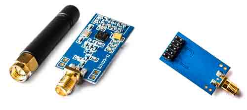
Sin embargo, os recomiendo que compréis los modelos con antena con conector estándar, que son algo más caros 2,30€ pero con mejor comportamiento.
Esquema de montaje
El CC1101 opera a 3.3V, y no es tolerante a 5V. La mayoría de módulos no incorporan ningún tipo de adaptación, por lo que conectarlos a 5V dañará el CC1101.
Si vuestro procesador es de 3.3V, como el ESP8266 o ESP32 no tendréis ningún problema. Pero, si vuestro procesador de 5V deberéis usar un adaptador de nivel lógico como vimos aquí.
Aparte de esto, el esquema de conexión es sencillo, ya que el CC1101 se emplea bus SPI para la comunicación. Por tanto, la conexión vista desde el procesador es la siguiente.
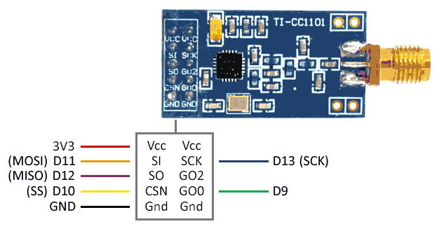
La conexión, vista desde Arduino será la siguiente.
Normalmente los módulos CC1101 no son compatibles a 5V. Si no es así, y vuestro procesador no es de 3.3V, tendréis que usar un adaptador de nivel lógico.
Ejemplos de código
Ejemplo básico
Para emplear el CC1101 usaremos la librería SmartRC-CC1101 disponible en este enlace.
La librería incorpora varios ejemplos de uso que conviene revisar. El código a continuación es un código simplificado a partir de los ejemplos de la librería.
Emisor
#include <ELECHOUSE_CC1101_SRC_DRV.h>

void setup(){

    Serial.begin(9600);

    if (ELECHOUSE_cc1101.getCC1101()){         // Check the CC1101 Spi connection.
    Serial.println("Connection OK");
    }else{
    Serial.println("Connection Error");
    }

    ELECHOUSE_cc1101.Init();              // must be set to initialize the cc1101!
    ELECHOUSE_cc1101.setCCMode(1);       // set config for internal transmission mode.
    ELECHOUSE_cc1101.setModulation(0);  // set modulation mode. 0 = 2-FSK, 1 = GFSK, 2 = ASK/OOK, 3 = 4-FSK, 4 = MSK.
    ELECHOUSE_cc1101.setMHZ(433.92);   // Here you can set your basic frequency. The lib calculates the frequency automatically (default = 433.92).The cc1101 can: 300-348 MHZ, 387-464MHZ and 779-928MHZ. Read More info from datasheet.
    ELECHOUSE_cc1101.setSyncMode(2);  // Combined sync-word qualifier mode. 0 = No preamble/sync. 1 = 16 sync word bits detected. 2 = 16/16 sync word bits detected. 3 = 30/32 sync word bits detected. 4 = No preamble/sync, carrier-sense above threshold. 5 = 15/16 + carrier-sense above threshold. 6 = 16/16 + carrier-sense above threshold. 7 = 30/32 + carrier-sense above threshold.
    ELECHOUSE_cc1101.setCrc(1);      // 1 = CRC calculation in TX and CRC check in RX enabled. 0 = CRC disabled for TX and RX.

    Serial.println("Rx Mode");
}
byte buffer[61] = {0};

void loop(){

    //Checks whether something has been received.
    //When something is received we give some time to receive the message in full.(time in millis)
    if (ELECHOUSE_cc1101.CheckRxFifo(100)){

    if (ELECHOUSE_cc1101.CheckCRC()){    //CRC Check. If "setCrc(false)" crc returns always OK!
    Serial.print("Rssi: ");
    Serial.println(ELECHOUSE_cc1101.getRssi());
    Serial.print("LQI: ");
    Serial.println(ELECHOUSE_cc1101.getLqi());

    int len = ELECHOUSE_cc1101.ReceiveData(buffer);
    buffer[len] = '\0';
    Serial.println((char *) buffer);
    for (int i = 0; i < len; i++){
    Serial.print(buffer[i]);
    Serial.print(",");
    }
    Serial.println();
    }
    }
}
Receptor
#include <ELECHOUSE_CC1101_SRC_DRV.h>

void setup(){

    Serial.begin(9600);

    if (ELECHOUSE_cc1101.getCC1101()){         // Check the CC1101 Spi connection.
    Serial.println("Connection OK");
    }else{
    Serial.println("Connection Error");
    }

    ELECHOUSE_cc1101.Init();              // must be set to initialize the cc1101!
    ELECHOUSE_cc1101.setCCMode(1);       // set config for internal transmission mode.
    ELECHOUSE_cc1101.setModulation(0);  // set modulation mode. 0 = 2-FSK, 1 = GFSK, 2 = ASK/OOK, 3 = 4-FSK, 4 = MSK.
    ELECHOUSE_cc1101.setMHZ(433.92);   // Here you can set your basic frequency. The lib calculates the frequency automatically (default = 433.92).The cc1101 can: 300-348 MHZ, 387-464MHZ and 779-928MHZ. Read More info from datasheet.
    ELECHOUSE_cc1101.setSyncMode(2);  // Combined sync-word qualifier mode. 0 = No preamble/sync. 1 = 16 sync word bits detected. 2 = 16/16 sync word bits detected. 3 = 30/32 sync word bits detected. 4 = No preamble/sync, carrier-sense above threshold. 5 = 15/16 + carrier-sense above threshold. 6 = 16/16 + carrier-sense above threshold. 7 = 30/32 + carrier-sense above threshold.
    ELECHOUSE_cc1101.setCrc(1);      // 1 = CRC calculation in TX and CRC check in RX enabled. 0 = CRC disabled for TX and RX.

    Serial.println("Rx Mode");
}
byte buffer[61] = {0};

void loop(){

    //Checks whether something has been received.
    //When something is received we give some time to receive the message in full.(time in millis)
    if (ELECHOUSE_cc1101.CheckRxFifo(100)){

    if (ELECHOUSE_cc1101.CheckCRC()){    //CRC Check. If "setCrc(false)" crc returns always OK!
    Serial.print("Rssi: ");
    Serial.println(ELECHOUSE_cc1101.getRssi());
    Serial.print("LQI: ");
    Serial.println(ELECHOUSE_cc1101.getLqi());

    int len = ELECHOUSE_cc1101.ReceiveData(buffer);
    buffer[len] = '\0';
    Serial.println((char *) buffer);
    for (int i = 0; i < len; i++){
    Serial.print(buffer[i]);
    Serial.print(",");
    }
    Serial.println();
    }
    }
}
Clonar dispositivo
Uno de los ejemplos más habituales al tratar con dispositivos 315/433Mhz es copiar señales existentes, como vimos en la entrada Copiar un mando inalámbrico 315/433Mhz con Arduino.
Podemos realizar esta misma función con el CC1101, con algunas de las siguientes librerías
RC-Switch
Es posible emplear la librería RC-Switch junto con el CC1101. Aquí tenéis un ejemplo
#include <ELECHOUSE_CC1101_SRC_DRV.h>
#include <RCSwitch.h>

int pin; // int for Receive pin.

RCSwitch mySwitch = RCSwitch();

void setup() {
  Serial.begin(9600);


#ifdef ESP32
pin = 4;  // for esp32! Receiver on GPIO pin 4.

#elif ESP8266
pin = 4;  // for esp8266! Receiver on pin 4 = D2.

#else
pin = 0;  // for Arduino! Receiver on interrupt 0 => that is pin #2

#endif

  ELECHOUSE_cc1101.Init();
  //ELECHOUSE_cc1101.setRxBW(812.50);  // Set the Receive Bandwidth in kHz. Value from 58.03 to 812.50. Default is 812.50 kHz.
  //ELECHOUSE_cc1101.setPA(10);
  ELECHOUSE_cc1101.setMHZ(433.92);

  mySwitch.enableReceive(pin);  // Receiver on interrupt 0 => that is pin #2
  ELECHOUSE_cc1101.SetRx();  // set Receive on
}

void loop() {
  if (mySwitch.available())
  {
    output(mySwitch.getReceivedValue(),
    mySwitch.getReceivedBitlength(),
    mySwitch.getReceivedDelay(),
    mySwitch.getReceivedRawdata(),
    mySwitch.getReceivedProtocol());
    mySwitch.resetAvailable();
  }
}
NewRemoteReceiver
También es posible usar la librería NewRemoteReceiver con el CC1101. Aquí tenéis un ejemplo
#include <ELECHOUSE_CC1101_SRC_DRV.h>
#include <NewRemoteReceiver.h>

int pin;

void setup() {
  Serial.begin(115200);


#ifdef ESP32
pin = 4;  // for esp32! Receiver on GPIO pin 4.

#elif ESP8266
pin = 4;  // for esp8266! Receiver on pin 4 = D2.

#else
pin = 0;  // for Arduino! Receiver on interrupt 0 => that is pin #2

#endif

  ELECHOUSE_cc1101.Init();            // must be set to initialize the cc1101!
  //ELECHOUSE_cc1101.setRxBW(812.50);  // Set the Receive Bandwidth in kHz. Value from 58.03 to 812.50. Default is 812.50 kHz.
  //ELECHOUSE_cc1101.setPA(10);
  ELECHOUSE_cc1101.setMHZ(433.92);
  ELECHOUSE_cc1101.SetRx();     // set Receive on

  NewRemoteReceiver::init(pin, 2, onReceived);
  Serial.println("Receiver initialized");
}

void loop() {

}

void onReceived(unsigned int period, unsigned long address, unsigned long groupBit, unsigned long unit, unsigned long switchType)
{
  Serial.print("Code: ");
  Serial.print(address);
  Serial.print(" Period: ");
  Serial.println(period);
  Serial.print(" unit: ");
  Serial.println(unit);
  Serial.print(" groupBit: ");
  Serial.println(groupBit);
  Serial.print(" switchType: ");
  Serial.println(switchType);

}
Descarga el código
Todo el código de esta entrada está disponible para su descarga en Github. 