What is an ADXL345 accelerometer?
The ADXL345 is a 3-axis micromachined capacitive accelerometer (3 DOF) that can be easily connected to a controller or processor like Arduino.
It is a capacitive micromachined sensor (MEMS) that detects acceleration in the X, Y, and Z axes. It is also possible to determine the orientation of the sensor, thanks to the force of gravity.
The ADXL345 is an ultra-low power device, with 45 µA in measurement mode and 0.1 µA in standby. It also has a FIFO memory block that stores up to 32 sets of X, Y, Z data.
Communication can be done through either SPI bus or I2C bus, making it easy to obtain the measured data. The supply voltage is low voltage between 2.0 to 3.6V.
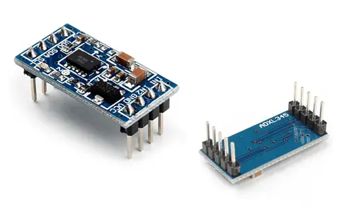
They are frequently integrated into modules that incorporate the necessary electronics to connect it easily to an Arduino. In most modules, this includes a voltage regulator that allows direct powering from 5V.
The ADXL345 has an adjustable measurement range between ±2g, ±4g, ±8g, ±16g, and a high resolution of up to 13 bits, with a sensitivity of 40mg/LSB in all ranges, which equates to an accuracy better than 1º.
The ADXL345 has two interrupt pins that can be configured to respond to certain events. These events include detecting rapid movements, impacts, and vibrations, in one or two pulses, and detecting free-fall 0-g conditions.
Accelerometers are widely used devices in all kinds of applications, from determining orientation in mobiles or tablets, detecting free-fall, measuring steps in pedometers, camera stabilization, alarms, and vibration sensors, among many others.
If you want to learn more about accelerometers, gyroscopes, and IMUs in Arduino, check out the series of posts How to use an accelerometer with Arduino, How to use a gyroscope with Arduino, and Measuring inclination with IMU.
Price
The ADXL345 is an inexpensive accelerometer. It can be found on mounting boards like the GY-291, which incorporates the necessary electronics to connect it easily to Arduino, for €1.10 from international sellers on eBay or AliExpress.
Despite being inexpensive, for similar prices we have IMUs like the MPU6050, which include accelerometer and gyroscope, and therefore have superior features and are more versatile.
Connection Diagram
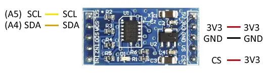
The connection is simple, we just power the module from Arduino using GND and 5V and connect the SDA and SCL pins of Arduino with the corresponding pins of the sensor.
While the connection from the Arduino side would look like this.
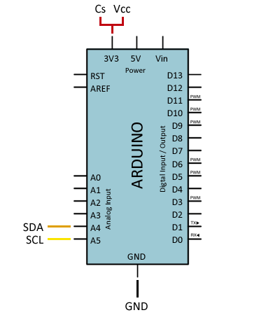
On Arduino Uno, Nano, and Mini Pro, SDA is pin A4 and SCK is pin A5. For other Arduino models, refer to the pinout diagram accordingly.
Verify that your board is compatible with 5V before connecting it to Arduino. If not, you will have to use a level shifter.
Code Examples
The following code reads the AXDL345 in raw format and displays the values on the serial port.
// Gnd      -  GND
// 3.3v     -  VCC
// 3.3v     -  CS
// Analog 4 -  SDA
// Analog 5 -  SLC

#include <Wire.h>

//Device address
const int DEVICE_ADDRESS = (0x53);

byte _buff[6];

//ADXL345 register addresses
char POWER_CTL = 0x2D;
char DATA_FORMAT = 0x31;
char DATAX0 = 0x32;  //X-Axis Data 0
char DATAX1 = 0x33;  //X-Axis Data 1
char DATAY0 = 0x34;  //Y-Axis Data 0
char DATAY1 = 0x35;  //Y-Axis Data 1
char DATAZ0 = 0x36;  //Z-Axis Data 0
char DATAZ1 = 0x37;  //Z-Axis Data 1

void setup()
{
  Serial.begin(57000);
  Serial.print("Started");

  Wire.begin();
  writeTo(DEVICE_ADDRESS, DATA_FORMAT, 0x01); //Set ADXL345 range to +- 4G
  writeTo(DEVICE_ADDRESS, POWER_CTL, 0x08);  //Set ADXL345
}

void loop()
{
  readAccel(); //Read acceleration x, y, z
  delay(500);
}

void readAccel() {
  //Read the data
  uint8_t numBytesToRead = 6;
  readFrom(DEVICE_ADDRESS, DATAX0, numBytesToRead, _buff);

  //Read register values and convert to int (Each axis has 10 bits, in 2 Bytes LSB)
  int x = (((int)_buff[1]) << 8) | _buff[0];
  int y = (((int)_buff[3]) << 8) | _buff[2];
  int z = (((int)_buff[5]) << 8) | _buff[4];
  Serial.print("x: ");
  Serial.print( x );
  Serial.print(" y: ");
  Serial.print( y );
  Serial.print(" z: ");
  Serial.println( z );
}

//Auxiliary write function
void writeTo(int device, byte address, byte val) {
  Wire.beginTransmission(device);
  Wire.write(address);
  Wire.write(val);
  Wire.endTransmission();
}

//Auxiliary read function
void readFrom(int device, byte address, int num, byte _buff[]) {
  Wire.beginTransmission(device);
  Wire.write(address);
  Wire.endTransmission();

  Wire.beginTransmission(device);
  Wire.requestFrom(device, num);

  int i = 0;
  while(Wire.available())
  {
    _buff[i] = Wire.read();
    i++;
  }
  Wire.endTransmission();
}
We can also use one of the many available libraries. For example, the Sparkfun library for the ADXL345. This library provides methods for communicating through both I2C and SPI, for configuring the ADXL345, and defining interrupts for activity, inactivity, single and double taps.
The library provides code examples, which are worth reviewing. The following example is a reduced version from those available in the library, which performs the same functions as the previous example with much more concise code.
#include <SPI.h>
#include <Wire.h>
#include <SparkFun_ADXL345.h>

ADXL345 adxl = ADXL345();

void setup()
{
  Serial.begin(9600);
  Serial.println("Start");
  Serial.println();

  adxl.powerOn();
  adxl.setRangeSetting(16);       //Set the range, values 2, 4, 8, or 16
}

void loop()
{
  //read the values and print them
  int x, y, z;
  adxl.readAccel(&x, &y, &z);
  Serial.print(x);
  Serial.print(", ");
  Serial.print(y);
  Serial.print(", ");
  Serial.println(z);
}
Download the Code
All the code from this post is available for download on Github. 