What is an IMU MPU-9150 or MPU-9250?
The MPU-9150 and MPU-9250 sensors are new generation 9DOF IMUs manufactured by Invensense. Both devices are part of the same family of components, with the MPU-9250 being the current and recommended model by the manufacturer.
Internally, the MPU-9250 incorporates an MPU-6500 IMU, which in turn consists of a 3DOF accelerometer and a 3DOF gyroscope, and a 3DOF magnetometer AK8963 manufactured by Asahi Kasei Microdevices Corporation. On the other hand, the MPU-9150 consists of an MPU-6050 IMU and an AK8975 magnetometer.
Communication in both models can be done through either SPI bus or I2C bus, making it easy to obtain the measured data. The supply voltage is low voltage between 2.4 to 3.6V.
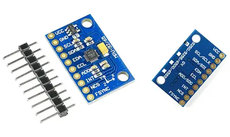
They are frequently integrated into modules that incorporate the necessary electronics to connect it easily to an Arduino. In most modules, this includes a voltage regulator that allows direct power to 5V.
It is a sensor that consumes 3.5mA, with all sensors and the DMP activated. It has a built-in temperature sensor, a high-precision clock, and programmable interrupts. It can also be connected to other I2C devices.
It has 16-bit analog-to-digital converters (ADC). The range of the accelerometer can be adjusted to ±2g, ±4g, ±8g, and ±16g, that of the gyroscope to ±250, ±500, ±1000, and ±2000°/sec, and that of the magnetometer up to ±4800µT.
The MPU-9250 incorporates an internal processor (DMP Digital Motion Processor) that executes complex MotionFusion algorithms to combine the measurements of the internal sensors, avoiding the need to perform the filters externally.
The MPU-9250 is a new generation IMU, which provides superior results compared to other IMUs such as the MPU-6050. By incorporating a magnetometer, the MPU-9250 eliminates the drift that can occur in other IMUs after a few hours of use.
Despite its higher price, we will use the MPU-9250 when we need an IMU with superior characteristics, for example, in vehicles or robots that require precision for extended periods of time.
If you want to learn more about accelerometers, gyroscopes, and IMUs in Arduino, check out the series of posts How to use an accelerometer with Arduino, How to use a gyroscope with Arduino, and Measuring inclination with IMU.
Price
The MPU-9250 is a sensor with a great quality-price ratio. It can be found for about €3.60, from international sellers on AliExpress or eBay.
Naturally, its price is much higher than 6DOF IMUs. However, it is one of the cheapest 9DOF IMUs.
Furthermore, compared to other 9DOF IMUs, it has the advantage of having all three sensors (accelerometer, gyroscope, and magnetometer) in the same integrated circuit, so its DMP can perform calculations and corrections with the measurements of the three sensors simultaneously.
In the remaining 9DOF IMUs, these calculations must be performed externally, which results in a loss of precision and performance.
Wiring diagram
The connection is simple, just power the module from Arduino using GND and 5V and connect the SDA and SCL pins of Arduino with the corresponding pins of the sensor.
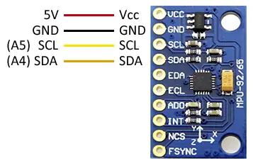
While the connection seen from the Arduino side would be as follows.
On Arduino Uno, Nano, and Mini Pro, SDA is pin A4 and SCK is pin A5. For other Arduino models, check the corresponding pinout scheme.
Verify that your board is compatible with 5V before connecting it to Arduino. If not, you will need to use a logic level shifter.
Code examples
The following example uses the I2C bus to read the RAW values from the MPU-9250.
//GND - GND
//VCC - VCC
//SDA - Pin A4
//SCL - Pin A5

#include <Wire.h>


#define    MPU9250_ADDRESS            0x68

#define    MAG_ADDRESS                0x0C


#define    GYRO_FULL_SCALE_250_DPS    0x00

#define    GYRO_FULL_SCALE_500_DPS    0x08

#define    GYRO_FULL_SCALE_1000_DPS   0x10

#define    GYRO_FULL_SCALE_2000_DPS   0x18


#define    ACC_FULL_SCALE_2_G        0x00

#define    ACC_FULL_SCALE_4_G        0x08

#define    ACC_FULL_SCALE_8_G        0x10

#define    ACC_FULL_SCALE_16_G       0x18

//Auxiliary function for reading
void I2Cread(uint8_t Address, uint8_t Register, uint8_t Nbytes, uint8_t* Data)
{
  Wire.beginTransmission(Address);
  Wire.write(Register);
  Wire.endTransmission();

  Wire.requestFrom(Address, Nbytes);
  uint8_t index = 0;
  while (Wire.available())
    Data[index++] = Wire.read();
}

// Auxiliary function for writing
void I2CwriteByte(uint8_t Address, uint8_t Register, uint8_t Data)
{
  Wire.beginTransmission(Address);
  Wire.write(Register);
  Wire.write(Data);
  Wire.endTransmission();
}

void setup()
{
  Wire.begin();
  Serial.begin(115200);

  // Configure accelerometer
  I2CwriteByte(MPU9250_ADDRESS, 28, ACC_FULL_SCALE_16_G);
  // Configure gyroscope
  I2CwriteByte(MPU9250_ADDRESS, 27, GYRO_FULL_SCALE_2000_DPS);
  // Configure magnetometer
  I2CwriteByte(MPU9250_ADDRESS, 0x37, 0x02);
  I2CwriteByte(MAG_ADDRESS, 0x0A, 0x01);
}

void loop()
{
  // ---  Read accelerometer and gyroscope ---
  uint8_t Buf[14];
  I2Cread(MPU9250_ADDRESS, 0x3B, 14, Buf);

  // Convert accelerometer registers
  int16_t ax = -(Buf[0] << 8 | Buf[1]);
  int16_t ay = -(Buf[2] << 8 | Buf[3]);
  int16_t az = Buf[4] << 8 | Buf[5];

  // Convert gyroscope registers
  int16_t gx = -(Buf[8] << 8 | Buf[9]);
  int16_t gy = -(Buf[10] << 8 | Buf[11]);
  int16_t gz = Buf[12] << 8 | Buf[13];

  // ---  Read magnetometer ---
  uint8_t ST1;
  do
  {
    I2Cread(MAG_ADDRESS, 0x02, 1, &ST1);
  } while (!(ST1 & 0x01));

  uint8_t Mag[7];
  I2Cread(MAG_ADDRESS, 0x03, 7, Mag);

  // Convert magnetometer registers
  int16_t mx = -(Mag[3] << 8 | Mag[2]);
  int16_t my = -(Mag[1] << 8 | Mag[0]);
  int16_t mz = -(Mag[5] << 8 | Mag[4]);

  // --- Show values ---

  // Accelerometer
  Serial.print(ax, DEC);
  Serial.print("\t");
  Serial.print(ay, DEC);
  Serial.print("\t");
  Serial.print(az, DEC);
  Serial.print("\t");

  // Gyroscope
  Serial.print(gx, DEC);
  Serial.print("\t");
  Serial.print(gy, DEC);
  Serial.print("\t");
  Serial.print(gz, DEC);
  Serial.print("\t");

  // Magnetometer
  Serial.print(mx + 200, DEC);
  Serial.print("\t");
  Serial.print(my - 70, DEC);
  Serial.print("\t");
  Serial.print(mz - 700, DEC);
  Serial.print("\t");

  // End measurement
  Serial.println("");

  delay(10);
}
Example with RTIMULIB-Arduino
Another option for reading the sensor is to use the RTIMULIB-Arduino library, which allows you to create an Attitude Heading Reference System (AHRS) and works with a wide variety of sensors. We saw how to use this library in this post.
Download the code
All the code from this post is available for download on Github. 