What is an ADS1115?
The ADS1115 is an external analog-to-digital converter (ADC) that we can connect to a processor like Arduino to measure analog signals.
Arduino has internal ADCs that we use when using the analog inputs of Arduino. In the Arduino Uno, Mini, and Nano models, we have 6 10-bit ADCs.
The ADS1115 provides 4 16-bit ADCs, 15 for measurement and one for the sign. The ADS1115 is connected via I2C, so it is easy to read. It has 4 addresses, which are selected by connecting the ADDRESS pin.
The interest in using an ADC like the ADS1115 is to obtain greater precision, in addition to relieving the processor of this burden. Also, in certain configurations, it is possible to measure negative voltages.
The ADS1115 has two measurement modes, single-ended and differential. In single-ended mode, we have four 15-bit channels. In differential mode, we use two ADCs for each measurement, so the number of channels is reduced to 2, but we will have the advantage of being able to measure negative voltages and greater immunity to noise.
It also has a comparator mode in which the ADS1115 generates an alert on the ALERT pin when any of the channels exceeds a threshold value that we set in the code.
Finally, the ADS1115 incorporates a PGA that allows us to adjust the gain from 6.144V to 0.256V. This allows us to obtain higher precision when measuring voltages lower than 5V.
Regardless of the selected PGA, the maximum voltage that we can measure will always be the supply voltage. That is, even if the PGA is 6.144V, we will not be able to measure voltages greater than 5V.
As we can see, the technical characteristics of the ADS1115 are much superior to the internal ADCs of Arduino. Therefore, they are suitable when we need precise measurements, such as in sensor readings, or when the signal can take negative values, as in current or voltage sensors.
Price
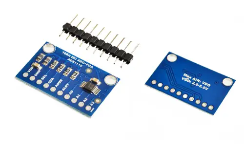
We can find modules with the ADS1115 ready to connect to Arduino for 1.80€ by searching in international sellers on eBay or AliExpress.
Assembly diagram
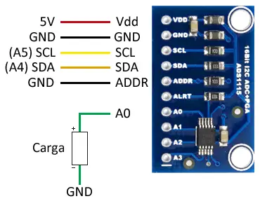
The connection is simple. On one hand, we power the module from Arduino using GND and 5V and connect the SDA and SCL pins of Arduino to the corresponding pins of the sensor.
The ADDR pin determines the I2C address of the device, according to the following table. The default mode is to connect the ADDR pin to GND, which results in the address 0x48.
| Address | ADDR Pin |
|---|---|
| 0x48 | GND |
| 0x49 | VDD |
| 0x4A | SDA |
| 0x4B | SCL |
For single-ended connection, we simply connect the load to be measured between GND and one of the 4 available pins.
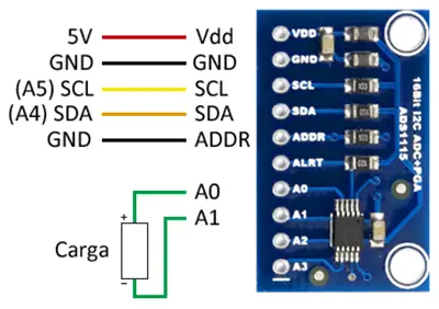
If instead we want the differential mode, we connect the load between A0 and A1 or between A2 and A3.
While, in both cases, the connection seen from the Arduino side would look like this.
In Arduino Uno, Nano, and Mini Pro, SDA is pin A4 and SCK is pin A5. For other models of Arduino, consult the pinout diagram accordingly.
The voltage to be measured should not exceed the gain set in the ADC, nor the Vcc +0.3V, or we can destroy the ADS1115.
Code examples
To perform the reading of the ADS1115, we will use the library developed by Adafruit, available at this link.
The library provides code examples, which is advisable to review. The following examples are modifications based on those available in the library
Single-ended mode
The following code shows the use of the single-ended mode. We perform the reading of the four channels and display the value on the serial port. To convert the value to voltage, it is necessary to use a multiplier, which in turn depends on the gain of the PGA that we have set.
#include <Wire.h>
#include <Adafruit_ADS1015.h>

Adafruit_ADS1115 ads;
const float multiplier = 0.1875F;

void setup(void)
{
  Serial.begin(9600);

  // Uncomment the one of interest
  // ads.setGain(GAIN_TWOTHIRDS);  +/- 6.144V  1 bit = 0.1875mV (default)
  // ads.setGain(GAIN_ONE);        +/- 4.096V  1 bit = 0.125mV
  // ads.setGain(GAIN_TWO);        +/- 2.048V  1 bit = 0.0625mV
  // ads.setGain(GAIN_FOUR);       +/- 1.024V  1 bit = 0.03125mV
  // ads.setGain(GAIN_EIGHT);      +/- 0.512V  1 bit = 0.015625mV
  // ads.setGain(GAIN_SIXTEEN);    +/- 0.256V  1 bit = 0.0078125mV
  ads.begin();
}

void loop(void)
{
  int16_t adc0, adc1, adc2, adc3;


  adc0 = ads.readADC_SingleEnded(0);
  adc1 = ads.readADC_SingleEnded(1);
  adc2 = ads.readADC_SingleEnded(2);
  adc3 = ads.readADC_SingleEnded(3);
  Serial.print("AIN0: "); Serial.println(adc0 * multiplier);
  Serial.print("AIN1: "); Serial.println(adc1 * multiplier);
  Serial.print("AIN2: "); Serial.println(adc2 * multiplier);
  Serial.print("AIN3: "); Serial.println(adc3 * multiplier);
  Serial.println(" ");

  delay(1000);
}
Differential mode
The following code shows the use of the differential mode. Like in the previous example, we can change the gain of the PGA, which in turn influences the multiplier used to convert the measurement to voltage.
#include <Wire.h>
#include <Adafruit_ADS1015.h>

Adafruit_ADS1115 ads;
const float multiplier = 0.1875F;

void setup(void)
{
  Serial.begin(9600);

  ads.begin();
}

void loop(void)
{
  int16_t results = ads.readADC_Differential_0_1();

  Serial.print("Differential: ");
  Serial.print(results);
  Serial.print(" ");
  Serial.print(results * multiplier);
  Serial.println("mV");

  delay(1000);
}
Comparator mode
The following code sets an alert on channel 0, which will be triggered when the recorded value exceeds 2.5 volts. To obtain the necessary value to set the alert, we will have to take into account the gain of the sensor.
#include <Wire.h>
#include <Adafruit_ADS1115.h>

Adafruit_ADS1115 ads;

void setup(void)
{
  Serial.begin(9600);

  ads.begin();

  // Activate comparator for 2.5V on channel 0
  // (Where 13333 = 2500 / 0.1875F)
  ads.startComparator_SingleEnded(0, 13333);
}

void loop(void)
{
  int16_t adc0;

  // Update comparators
  adc0 = ads.getLastConversionResults();
  Serial.print("AIN0: "); Serial.println(adc0);

  delay(100);
}
Download the code
All the code in this post is available for download on Github. 
