What is a 28BYJ-48 motor and a ULN2003?
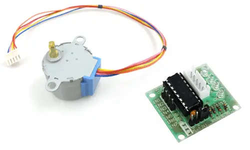
The 28BYJ-48 is an inexpensive small unipolar stepper motor. The electrical characteristics of the 28BYJ-48 are modest, but it incorporates an integrated reducer that makes it a much more useful and interesting component.
The 28BYJ-48 has a step of 5.625 degrees (64 steps per revolution). The internal reducer has a 1/64 ratio. Combined, the total accuracy is 4096 steps per revolution, equivalent to a step of 0.088º, which is very high precision.
In reality, the reducer ratio is not exactly 1/64 so the number of steps is 4076 per revolution (equivalent to a reducer of 1/63.6875)
The motor can be powered by 5V or 12V, with the 5V model being more common. Physically, both models are identical, so to know the nominal voltage, you should check the motor label.
The 28BYJ-48 has a maximum torque after the reducer of 3N•cm (0.3Kgf•cm). The maximum frequency is 100Hz, which is about 40 seconds per revolution, or equivalently a maximum rotation speed of around 1.5 rpm.
The resistance and electrical consumption vary with the 28BYJ-48 model. In the 5V models, it is 60 Ohms, resulting in a consumption of 83mA. The 12V models have resistances of 130-380 Ohms and consumption of 71 to 32mA.
For control, we can use a board with the ULN2003 integrated. Normally the 28BYJ-48 is supplied with this board, and both devices have terminals for easy connection.
The 28BYJ-48 is widely used in industrial applications, such as the control of hydraulic and pneumatic valves.
In the field of hobbies, we can use the 28BYJ-48 to make small articulated robots, robotic arms, position sensors, or rotate the table of a scanner.
PRICE
The 28BYJ-48 is a very cheap motor. We can find 28BYJ-48 for around 1.2€ from international sellers on eBay or AliExpress.
Normally, you will want to acquire it together with the ULN2003 controller. You can find kits with both components together for 1.60€.
HOW DOES THE 28BYJ-48 WORK WITH ULN2003?
For the control of the 28BYJ-48, we will use a board with the ULN2003 integrated. The ULN2003 is a group of 7 Par Darlington of which we will use 4, one for each phase of the stepper motor.
A Darlington pair is a device that allows us to supply a higher current than we could using the outputs of Arduino directly.
More information at
The 28BYJ-48 is a unipolar motor, so we do not need to reverse the current passing through the coils to make it work. Therefore, we do not need a complicated controller like the A4988 or the DRV8825, not even a simple H-bridge like the L298N.
Applying an all-or-nothing control, that is, turning on or off a coil completely, we only need to activate the coils in the correct sequence.
There are several possible sequences, and we will now see the three most commonly used.
1-phase sequence
In the 1-phase sequence, we turn on a single coil each time.
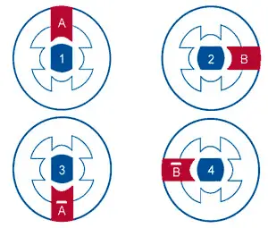
Taking this activation sequence to a table, which we will later use for the code, the sequence would be as follows,
| Step | A | B | A’ | B’ |
|---|---|---|---|---|
| 1 | ON | OFF | OFF | OFF |
| 2 | OFF | ON | OFF | OFF |
| 3 | OFF | OFF | ON | OFF |
| 4 | OFF | OFF | OFF | ON |
2-phase sequence
In the 2-phase sequence, we turn on two consecutive coils in each phase. By making two coils work simultaneously in each step, the generated magnetic field is higher (41% more), so the motor has more torque and, in general, behaves better. As a negative point, we double the energy consumption.
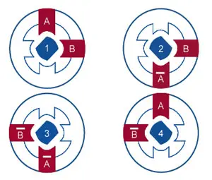
Expressed in a table, it results in,
| Step | A | B | A’ | B’ |
|---|---|---|---|---|
| 1 | ON | ON | OFF | OFF |
| 2 | OFF | ON | ON | OFF |
| 3 | OFF | OFF | ON | ON |
| 4 | ON | OFF | OFF | ON |
Half-step sequence
The last sequence we are going to see is the half-step sequence. Here we alternately turn on one and two coils.
With this sequence, we achieve half-step precision. The developed torque varies since in some steps we activate two coils and in others only one, but at the same time, the rotation is more “guided”, so in general, both effects are compensated and the operation is good, except in applications where we are very close to the maximum torque.
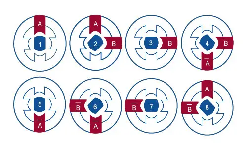
Expressing the sequence in the form of a table results in
| Half-step | A | B | A’ | B’ |
|---|---|---|---|---|
| 1 | ON | OFF | OFF | OFF |
| 2 | ON | ON | OFF | OFF |
| 3 | OFF | ON | OFF | OFF |
| 4 | OFF | ON | ON | OFF |
| 5 | OFF | OFF | ON | OFF |
| 6 | OFF | OFF | ON | ON |
| 7 | OFF | OFF | OFF | ON |
| 8 | ON | OFF | OFF | ON |
Assembly diagram
The connection of the 28BYJ-48 to Arduino through the ULN2003 module is quite simple.
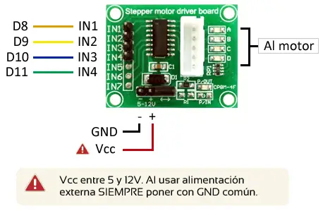
First, we connect the 28BYJ-48 to the board with the ULN2003 integrated with the built-in connection terminal. The terminals only fit in one position, so there is no risk of connecting it incorrectly.
On the other hand, we power the module by applying the supply voltage between Vcc and GND of the module. There are 28BYJ-48 models with nominal voltages of 5 or 12V. You should apply the voltage that corresponds to your motor.
In the case of motors with a nominal voltage of 5V, we can power directly from the 5V output of Arduino.
Do not exceed the supply voltage of your 28BYJ-48 model, or you will permanently damage it.
Finally, we connect the IN1, IN2, IN3, and IN4 pins to four digital outputs of Arduino. When activating each of the signals, we will activate the corresponding Darlington pair, causing the coil to turn on.
The connection, seen from Arduino, would be as follows,
Operating a unipolar stepper motor is not difficult, we just have to use the sequences we have seen correctly.
However, it is a code in which it is convenient for us to be (at least) moderately organized, or it can start to grow in the number of lines quickly, making it slower, more difficult to use, and maintain.
On the one hand, since we are going to use the code frequently to change the step in one direction or the other, it is convenient to isolate it in two independent functions, clockwise() and anticlockwise()
On the other hand, we are going to store the activation sequence in a lookup table. The code contains the three sequences, simply uncomment the one you want to use. By default, the half-step sequence is uncommented, which is recommended by the manufacturer.
Finally, we have a setOutput() function that sets the output to the motor at a specific step of the sequence.
//pin definition
const int motorPin1 = 8;    // 28BYJ48 In1
const int motorPin2 = 9;    // 28BYJ48 In2
const int motorPin3 = 10;   // 28BYJ48 In3
const int motorPin4 = 11;   // 28BYJ48 In4

//variable definition
int motorSpeed = 1200;   //variable to set the speed
int stepCounter = 0;     // step counter
int stepsPerRev = 4076;  // steps for a full revolution

//tables with the activation sequence (uncomment the one you need)
//1-phase sequence
//const int numSteps = 4;
//const int stepsLookup[4] = { B1000, B0100, B0010, B0001 };

//2-phase sequence
//const int numSteps = 4;
//const int stepsLookup[4] = { B1100, B0110, B0011, B1001 };

//half-step sequence
const int numSteps = 8;
const int stepsLookup[8] = { B1000, B1100, B0100, B0110, B0010, B0011, B0001, B1001 };

void setup()
{
  //declare pins as output
  pinMode(motorPin1, OUTPUT);
  pinMode(motorPin2, OUTPUT);
  pinMode(motorPin3, OUTPUT);
  pinMode(motorPin4, OUTPUT);
}

void loop()
{
  for (int i = 0; i < stepsPerRev * 2; i++)
  {
    clockwise();
    delayMicroseconds(motorSpeed);
  }
  for (int i = 0; i < stepsPerRev * 2; i++)
  {
    anticlockwise();
    delayMicroseconds(motorSpeed);
  }
  delay(1000);
}

void clockwise()
{
  stepCounter++;
  if (stepCounter >= numSteps) stepCounter = 0;
  setOutput(stepCounter);
}

void anticlockwise()
{
  stepCounter--;
  if (stepCounter < 0) stepCounter = numSteps - 1;
  setOutput(stepCounter);
}

void setOutput(int step)
{
  digitalWrite(motorPin1, bitRead(stepsLookup[step], 0));
  digitalWrite(motorPin2, bitRead(stepsLookup[step], 1));
  digitalWrite(motorPin3, bitRead(stepsLookup[step], 2));
  digitalWrite(motorPin4, bitRead(stepsLookup[step], 3));
}
Download the code
All the code from this post is available for download on Github.
