We continue with our PCB design tutorial section by looking at PTH and SMD components, their differences, as well as the advantages and disadvantages of each technology.
In previous posts we have already seen what a PCB is, what its parts are, what layers are and the importance of vias, and briefly introduced the manufacturing process of a PCB.
By now we should be losing our “fear” of the PCB concept, and it should be clear that a PCB is nothing more than a simple, cheap, and compact way to replace the wiring of an electronic circuit.
In addition to the PCB we must add the electronic components themselves. Together, the PCB’s conductor tracks and the components will form the designed electronic circuit.
Now that we have introduced PCBs, it’s time to talk about electronic components. As we had already mentioned, there are two main families of components: PTH and SMD, depending on how they are mounted on the PCB.
You will also see them referred to by the terms THT (Through Hole Technology) and SMT (Surface Mounted Technology).
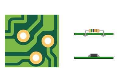
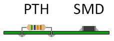
PTH (plated-through holes) components are mounted by inserting them into holes in the PCB where the conductor is left exposed around the perimeter, and then soldered.
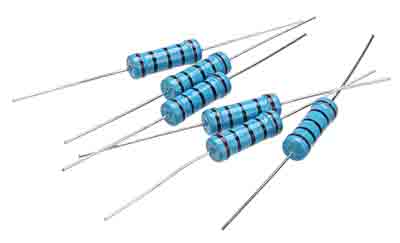
You are probably familiar with this type of component. They are the ones we most frequently encounter when learning electronics, or on domestic boards, as these are the components used on a breadboard.
On the other hand, SMD (Surface Mounted Device) components are mounted on the surface of the PCB, without the need for holes. For this, areas of exposed conductor are left, which, as we saw, we call pads.
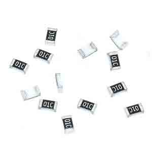
You have also seen SMD components many times. Every time you see an “industrial” board when disassembling a commercial device, most of the components you will find are SMD.
Advantages of PTH and SMD
Of course, as it could not be otherwise, each component technology has its own advantages and disadvantages. Otherwise, one would simply have completely replaced the other.
So let’s briefly look at the advantages of each one, and when their use is appropriate.
Conclusion
We have seen both families of components, PTH and SMD. We have seen that, in summary, PTH components are easier to handle by hand, while SMD components are smaller and cheaper.
The advice is to start in the world of electronics with PTH components, because they are easier to solder. Furthermore, you can test the circuit on a breadboard, or even solder it on a protoboard.
But if you get into the world of PCBs, switch to SMD technology as soon as you can. In the end, the larger SMD sizes, which we will see in the next post, are not that difficult to solder by hand. Your circuits will look much more professional, small, and cheap.
That’s it for this introductory post on components. In the next post, we will briefly review some of the electronic components we will commonly encounter when designing PCBs.
And you, what do you prefer, PTH or SMD components? If you’d like to share your opinion, feel free to leave us a comment!
