In previous posts, we have seen how to use the digital inputs of our Arduino. In this post, we are going to look at analog inputs, their operation and characteristics.
Analog inputs work in a similar way to digital inputs, so in practice the final setup and code are very similar.
However, internally, in many aspects they are radically different. Therefore, to correctly understand their use and functionality, it is necessary to see a minimum of theory.
What is an analog input?
Analog inputs work with analog signals. So first we need to see what an analog signal is (and its differences from digital signals).
An analog signal is a magnitude that can take any value within an interval –Vcc and + Vcc. For example, an analog voltage signal between 0V and 5V could be 2.72V, or 3.41V (or any other value with any number of decimals).
In contrast, recall that a theoretical digital voltage signal could only register two values, which we called LOW and HIGH (in the example, 0V or 5V).
As a general rule in controllers, analog inputs are scarcer, slower, and more expensive than digital inputs. In the case of Arduino Uno, we have a variable number of analog inputs, which for Arduino Uno and Mini Pro are 6, and for Arduino Mega are 16.
This is a more than respectable number of analog inputs, which rivals or surpasses traditional controllers of much higher cost (analog inputs are usually expensive).
It is important to understand that in the real world any voltage signal that we can measure will always be analog. A digital value is a concept, an abstraction.
As we saw when explaining digital inputs, a digital input is a process of transformation to digital. For this, a value HIGH is assigned to measurements that exceed a threshold value, and LOW to those that fall below.
Well, analog inputs provide a measurement encoded in the form of a digital number (for example from 0 to 255).
That is, the measurement provided by an analog input is also a digital value, so it is equally an abstraction. This leads us to the concept of measurement precision 👇.
Measurement Precision
To understand the precision of an analog input, it is necessary to understand how an analog-to-digital converter (ADC) works, which is its fundamental component. An ADC is a device that converts an analog measurement into a digital measurement encoded with an N-bit number.
There are many ways to build an ADC, but the important thing is to understand that we do not actually measure the analog value with all its decimals, but we “classify” it within 2^N levels, which define 2^N-1 intervals.
The width of this interval measured in mV is the precision of the signal. The greater the number of bits, the greater the number of intervals, the smaller the width of the interval, and therefore the better the measurement precision.
In the case of Arduino Uno, Mini Pro, and Mega, the analog inputs have a 10-bit resolution, which provides 1024 digital levels, which at 5V implies a measurement precision of +-2.44mV. Arduino Due has a 12-bit resolution, 4096 digital levels, which implies a precision of 0.61 mV.
Relative Precision
So far we have assumed a controller powered between 0V and 5V, measuring an analog voltage signal between 0V and 5V. In this case, with a 10-bit ADC we have a precision of 4.88mV, which implies a relative precision with respect to the input signal of 0.1% (1/1024).
However, suppose we measure a signal that varies between 0V and 1V. In this case, with the same 10-bit ADC we would have the same absolute precision of 4.88mV, but a lower relative precision with respect to the signal, which would drop to 0.5%.
That is, if we take a measurement of a signal that varies within a limit lower than Vcc, we are losing relative precision. This is the consequence of not using the entire measurement range, so in reality the ADC behaves as if it had a lower number of bits.
Analog Reference Voltage (aref)
To solve this situation, Arduino allows changing the voltage taken as a reference by the analog-to-digital converter.
The reference value is changed with the AnalogRef function, and the possible values are:
DEFAULT: Default value, corresponding to Vcc (5V or 3.3V, depending on models)INTERNAL: Corresponds to 1.1V (in Atmega 168 and 328)EXTERNAL: Voltage applied externally to the Vref pin (always between 0 and Vcc)INTERNAL1V1andINTERNAL2V56, corresponding to 1.1V and 2.56V (only in Mega)
In the case of using the external voltage reference (EXTERNAL), if we know with absolute certainty that a signal will not exceed a certain voltage value, for example 0.7V, we can provide this value as a reference through the Aref Pin. The measurement will be performed taking this voltage as a reference instead of Vcc, so we recover all the relative precision.
If we modify the reference voltage, we must define the mode using the AnalogRef function before performing any analog reading.
If we introduce a voltage value on the Aref pin, we must not exceed this value on the analog inputs. Furthermore, in no case should we exceed the Arduino supply voltage. Otherwise, we could damage the analog pins.
Connecting Analog Inputs in Arduino
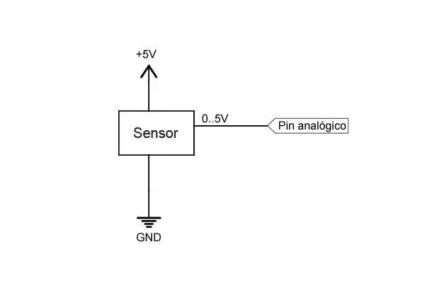
Suppose we have an analog sensor that provides an analog signal between 0V and 5V. The connection diagram is similar to the one we used for digital reading.
Arduino Code
The code to perform the reading is really simple, and similar to what we saw for digital inputs. We simply perform the reading using AnalogRead() and store the returned value.
const int sensorPin = A0;    // select the input for the sensor
int sensorValue;     // variable that stores the raw value (0 to 1023)

void setup()
{
  Serial.begin(9600);
}

void loop()
{
  sensorValue = analogRead(sensorPin);   // perform the reading

  //send message to serial port based on the read value
  if (sensorValue > 512)
  {
    Serial.println("Greater than 2.5V");
  }
  else
  {
    Serial.println("Less than 2.5V");
  }
  delay(1000);
}
The value returned by the AnalogRead() function is encoded as an integer from 0 to 1023. If we want to convert this value into a voltage value, we can use the following variation:
const int sensorPin = A0;   // select the input for the sensor
int sensorValue;      // variable that stores the raw value (0 to 1023)
float value;        // variable that stores the voltage (0.0 to 5.0)

void setup()
{
  Serial.begin(9600);
}

void loop()
{
  sensorValue = analogRead(sensorPin);        // perform the reading
  value = fmap(sensorValue, 0, 1023, 0.0, 5.0);   // change scale to 0.0 - 5.0

  Serial.println(value);              // display the value on serial
  delay(1000);
}

// scale change between floats
float fmap(float x, float in_min, float in_max, float out_min, float out_max)
{
  return (x - in_min) * (out_max - out_min) / (in_max - in_min) + out_min;
}
However, keep in mind that floating-point operations (with decimals) are much slower than with integers, so try to avoid having to perform this conversion and work with integers whenever possible.
Sampling Frequency
With the code used, the sampling frequency is approximately 9600 Hz, that is, about 100 microseconds per measurement.
In comparison, the digitalRead function has a frequency of 15000Hz, about 66 microseconds per measurement, slightly faster.
Hooowever… using other codes, the analog reading can be increased to approximately 1.5 Mhz, or 660 nanoseconds per input.
While (playing around) digital inputs can be accelerated to almost 15 Mhz, 66 nanoseconds, by reading all inputs simultaneously.
Therefore, we see that digital inputs can actually be much faster than analog ones.
Reading Values Greater Than 5V
If we need to read an input with a voltage level higher than 5V, for example 12V, we must perform a voltage adaptation. The best way to perform the adaptation is to use a simple voltage divider.
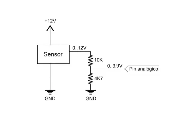
With this configuration, the digital pin of Arduino will receive a voltage that varies between 0 and 3.84V, so, as we have explained, we would be losing relative precision. One option would be to adjust the resistors so that the limits are as close as possible to 0 and 5V, or use another voltage divider to power the Aref pin.
The resistor values to use depend on the voltage we want to read and the impedance of the sensor.
In general, they must meet the following conditions:
- Convert the signal into a range lower than but similar to the supply voltage.
- Be much higher than the equivalent impedance of the device to be measured.
- Negligible compared to the Arduino input impedance.
- Limit the current flowing through them to minimize losses.
- Be able to dissipate the power they will handle.
You can use the voltage divider calculator to calculate resistor values that meet these requirements.
Do not use this system to read voltages above 35V, or for alternating current devices without being very sure of what you are doing. It is very likely that the resistors will not hold up.
In the next post, we will see how to use analog inputs to read the state of a potentiometer or the value of a variable resistor, something common when reading sensors whose reading is done by measuring their resistance.
Download the Code
All the code from this post is available for download on Github. 
