In this previous post we saw how to use PWM outputs to simulate an analog voltage output.
However, we made it very clear that a PWM output is not an analog voltage signal, but rather a pulsed digital signal whose average value is the desired value. Not knowing this can cause unexpected behavior in the components we connect to the PWM signal, or even damage them.
As we said, for a component expecting an analog voltage signal to receive a PWM is similar to asking for a gentle head massage, and getting hit with a hammer every 20 seconds (the average will be the same but… it’s not the same thing).
There are several mechanisms we can use to improve the response of our PWM, so that it better approximates a true analog signal. One of the simplest is to use a low-pass filter to “smooth” the signal.
In this post we will see how to incorporate a low-pass filter into a PWM output to improve its behavior and make the resulting output better approximate a true analog signal.
Incorporating a Low-Pass Filter
A PWM output is a mechanism frequently incorporated by microcontrollers to emulate an analog signal. It consists of providing a pulsed signal at a certain frequency, whose average value is the desired analog value. But the actual voltage value applied is, at all times, a digital signal between -Vcc and +Vcc.
For example, with a Vcc voltage of 5V, if we want a 1V PWM signal, a signal will be generated that is at 5V for 20% of the time and at 0V for the remaining 80%.
If the system’s response is slow compared to the PWM frequency, the PWM output may be sufficient. On the other hand, in other cases it will not be, and we could even damage the powered component if the Vcc voltage is higher than the component’s maximum allowable voltage.
To improve the response of the analog output we have several options, and the simplest is to incorporate a passive low-pass filter using an RC network.
A low-pass filter is a component that removes high frequencies from a signal, allowing low frequencies to pass.
The electrical schematic is as follows, where we see that we have superimposed the RC filtering network between the PWM output and the filtered signal, which is the one received by the load.
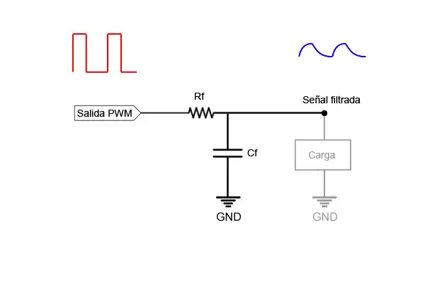
As we anticipated, the system’s response is a damped version of the PWM signal, but it still is not a perfect analog signal. An example of the response is the following:
We must observe that the produced signal has two relevant parameters.
- Response time: The time it takes for the signal to reach the steady state (a certain percentage of the desired signal)
- Ripple: The small oscillation that remains after the filter.
These two effects are “opposite” to each other. That is:
- If we try to reduce the ripple, we will need very long response times.
- If we try to reduce the response time, we must accept a higher ripple.
Therefore, there is no single optimal filter and signal. We will have to make a design decision and accept a compromise between a certain ripple value and a response time.
Adjusting R and C in the Low-Pass Filter
The characteristics of the response will depend on:
- The PWM frequency
- The voltages of the filtered signal and the desired signal
- The chosen values of R and C
To calculate these parameters, and to graphically visualize the obtained response, we can use the RC network calculator available at this link.
Limitations of a Passive Filter
The proposed low-pass filter is useful for providing an almost analog voltage value, and even for powering small loads. However, it is not suitable for powering large loads.
Higher power loads have lower impedances. When this impedance is lower than that of the RC network, the load’s consumption causes the obtained signal to deviate from the theoretical one.
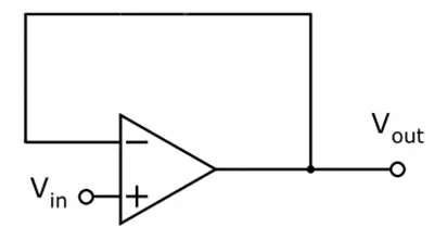
A simple way to avoid this is to use an operational amplifier to make a voltage follower, which isolates the load’s influence from the operation of the RC network.
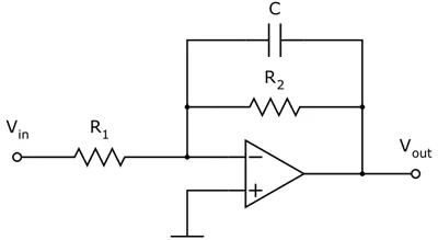
However, since we are going to use an operational amplifier, we could unify both components by using an active filter.
Finally, another highly recommended option is to directly use one of the many commercially available ADC converters. We will see these solutions in future posts.