In previous tutorials we have seen how to use digital inputs and analog inputs to receive signals from the world. We have also seen how to interact with the environment using digital outputs.
However, sometimes a digital signal (ON/OFF) will not be enough, and we will need to provide an analog voltage value. **(for example, to regulate the brightness of an LED, or vary the speed of a DC motor)*.
In this post we are going to see how to use a PWM output to emulate an analog voltage signal from Arduino.
How does an analog output work?
Analog outputs are a bit more complicated than digital ones (as was already the case with analog and digital inputs).
The first thing we need to understand is that most automation devices (and Arduino is no exception) are not capable of providing a true analog output. They cannot even supply a discretized (i.e., stepped) analog voltage output.
The only thing they can provide are digital outputs of -Vcc or Vcc. (for example, 0V and 5V)
To overcome this limitation and simulate an analog output, most automation devices use a “trick”, which consists of activating a digital output for a period of time and keeping it off for the rest.
The average of the output voltage, over time, will be equal to the desired analog value.
Saying that a PWM output is an analog output is like saying that getting hammered on the head is, on average, the same pressure as getting a massage
There is more than one way to make this approximation. One of the simplest, and therefore widely used in automation, is Pulse Width Modulation (PWM).
In this modulation, the frequency (i.e., the time between pulse triggers) is kept constant, while the pulse width is varied.
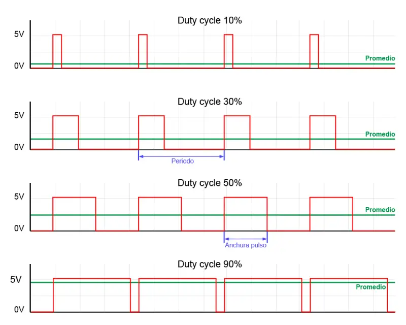
The proportion of time the signal is on, relative to the total cycle time, is called the Duty cycle. It is usually expressed as a percentage.
It is immediately deducible that the average signal is the product of the maximum voltage and the DutyCycle, according to the following expression.
Similarly, we have that
PWM is not an analog signal
It is important to remember at all times that in a PWM output the actual voltage value is Vcc (what I told you before about hammering your head).
For example, if we are powering a device that needs 3V, and we use a pulsed signal, we will actually be supplying 5V for 60% of the time and 0V for 40%.
But if the device, for example, supports a maximum of 3V, we can damage it if we power it via PWM.
A pulsed signal is sufficient to emulate an analog signal in many applications. For example, we can vary the light intensity of an LED using PWM. The LED actually turns on and off several times per second, but this flicker is so fast that the eye does not perceive it. The overall perceived effect is that the LED shines with less intensity.
Another example is varying the speed of a DC motor with PWM. In most cases, the inertia of the motor will make the effect of the PWM negligible. However, depending on the frequency, we may notice vibrations or noise, in which case we should vary the PWM frequency.
On the other hand, we must consider the effects that the rapid connection and disconnection of the pulsed signal may have on the powered device. For example, in the case of inductive loads (motors, relays, or electromagnets), disconnection will cause induced voltage that can damage the digital output or the device itself, so it will be necessary to have appropriate protections.
Regarding transistors, in general, BJT type transistors are suitable for operating as PWM signal amplifiers. This is usually not the case with MOS transistors, where the capacitive effects of the transistor, combined with the current limitation of digital outputs, will often require a prior amplification driver to prevent the transistor from operating in the active region.
Improper use of a PWM signal can damage the powered device if it does not support the applied Vcc voltage.
Analog outputs in Arduino
Arduino implements hardware PWM outputs on several of its pins, which are identified on the board with the ~ symbol next to the pin number.
- On Arduino Uno, Mini, and Nano, we have 6 8-bit PWM outputs on pins 3, 5, 6, 9, 10, and 11.
- On Arduino Mega we have 15 8-bit PWM outputs on pins 2 to 13 and 44 to 46.
- Arduino Due has 13 8-bit PWM outputs on pins 2 to 13. Additionally, this board incorporates two discretized analog outputs (DAC) with 12-bit resolution (4096 levels).
We can also emulate PWM signals by software, but with the additional workload this implies for the processor.
An 8-bit resolution on a PWM output means we have 256 levels. That is, we indicate the Duty cycle using a number from 0 to 255.
Timers in hardware PWM
Hardware PWM functions use Timers to generate the output waveform. Each Timer serves 2 or 3 PWM outputs. For this, it has a comparison register for each output. When the timer reaches the value of the comparison register, the output inverts its value.
Each output connected to the same timer shares the same frequency, although they can have different Duty cycles, depending on the value of their comparison register.
Incompatibilities
The use of Timers is not exclusive to PWM outputs, but is shared with other functions. Using functions that require the use of these Timers will mean that we cannot use some of the PWM pins simultaneously.
Below are some of the most frequent incompatibilities.
The servo library makes intensive use of timers, so while we are using it, we will not be able to use some of the PWM outputs.
In the case of Arduino Uno, Mini, and Nano, the servo library uses Timer 1, so we cannot use pins 9 and 10 while using a servo.
In the case of Arduino Mega, it will depend on the number of servos we use.
- If we use less than 12 servos, it uses Timer 5, so we will lose pins 44, 45, and 46.
- For 24 servos, it uses Timers 1 and 5, so we will lose pins 11, 12, 44, 45, and 46.
- For 36 servos, it uses Timers 1, 3, and 5, losing pins 2, 3, 5, 11, 12, 44, 45, 46.
- For 48 servos, it uses Timers 1, 3, 4, and 5, losing all PWM pins.
On Arduino Uno, Mini, and Nano, pin 11 is also used for the MOSI function of SPI communication. Therefore, we cannot use both functions simultaneously on this pin. Arduino Mega does not have this problem, as they are on different pins.
The Tone function uses Timer 2, so we cannot use pins 3 and 11, and on Arduino Mega pins 9 and 10.
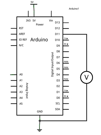
Wiring Diagram
For this tutorial, no wiring is necessary. However, we can verify the correct operation of the analog outputs simply by measuring the voltage between the digital output and GND with a multimeter.
Code Example
The code needed to turn on a PWM output is very simple thanks to Arduino’s libraries, which configure the PWM outputs by default in the Setup function, hiding the difficulty of manipulating the Timers.
Thus, in the most basic example, we simply define the PWM pin we want to use, and use the analogWrite function to write the Duty Cycle value, measured from 0 to 255.
The following code progressively increases the value of an analog signal from 0 to 255. When it reaches the maximum value, the counter will go to 0, so the cycle will start again.
const int analogOutPin = 5; // Analog output pin

byte outputValue = 0;        // PWM value

void setup() {
}

void loop() {
  analogWrite(analogOutPin, outputValue);
  delay(10);
  outputValue++;
}To visualize the previous code we can use a voltmeter or an LED placed on pin 11. However, we can modify the previous code with a small trick, to transfer the PWM value to another signal, and thus visualize it on the built-in LED on the board on pin 13.
Don’t focus on the interrupt part, just on the Loop() function. The rest of the code is a bit complex for this post. Just understand that it’s a trick to show a PWM on the built-in LED, making our tests easier.
const int analogOutPin = 11; // Analog output pin that the LED is attached to
byte outputValue = 0;

void setup()
{
  bitSet(DDRB, 5);      // LED pin (13)
  bitSet(PCICR, PCIE0);       // enable pin change interrupts on bank 0
  bitSet(PCMSK0, PCINT3);     // enable PCINT3 (PB3) pin change interrupt
}

void loop()
{
  analogWrite(analogOutPin, outputValue);
  delay(10);
  outputValue++;
}

ISR(PCINT0_vect)
{
  if(bitRead(PINB, 3))
  {
    bitSet(PORTB, 5);   // LED on
  }
  else
  {
    bitClear(PORTB, 5); // LED off
  }
} Finally, if we combine the previous code with what we saw in serial port communication, we can make a program that receives a digit from 0 to 9, and varies the intensity of the built-in LED on the board.
const int analogOutPin = 11;
byte outputValue = 0;

void setup()
{
   Serial.begin(9600);         // Start serial port
   pinMode(ledPIN , OUTPUT);

   bitSet(DDRB, 5);      // LED pin (13)
   bitSet(PCICR, PCIE0);       // enable pin change interrupts on bank 0
   bitSet(PCMSK0, PCINT3);     // enable PCINT3 (PB3) pin change interrupt
}

void loop()
{
   if (Serial.available()>0)  // If there are available data
   {
      outputValue = Serial.read();  // Read the option
      if(outputValue >= '0' && outputValue <= '9')
      {
         outputValue -= '0';    // Subtract '0' to convert to a number
         outputValue *= 25;    // Multiply by 25 to convert to a scale of 0 to 250
         analogWrite(ledPIN , outputValue);
      }
   }
}

ISR(PCINT0_vect)
{
   if(bitRead(PINB, 3))
   {
      bitSet(PORTB, 5);   // LED on
   }
   else
   {
      bitClear(PORTB, 5); // LED off
   }
} Download the code
All the code from this post is available for download on Github.

