What is an IC2262 remote control?
The IC2262 is a 4-channel digital radio frequency remote control that we can connect to a processor like Arduino to execute actions remotely.
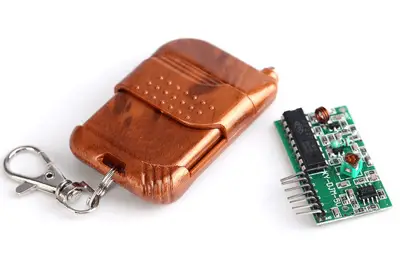
These types of controls are made up of the transmitter (2262) that is integrated into a remote control with four buttons, and a receiver (2272) in the form of a module that we can easily connect to Arduino.
The IC2262 remote works at a frequency of 315 Mhz, which is a free band. The range, according to specifications, is 50-100m, but in practice the maximum range is 1 to 5 meters.
On the other hand, they do not have a filter or hardware ID, so if we want robust communication, we will have to implement it by software.
In short, they are low-priced and low-specification devices that do not have the features of other wireless systems, although for certain home projects they may be sufficient.
We can use these types of controls in our projects to turn a device on or off remotely, open doors, control a sound or video system, or control lighting.
Communication with these controls cannot be considered secure. Do not use them in security applications, such as electronic locks, automatic door opening, or alarm control, or in applications where the safety of people depends.
Price
These types of controls are quite cheap. We can find 4-channel remote controls with transmitter 2262 and receiver module 2272 for 1.70€ from international sellers on Ebay and Aliexpress.
Assembly diagram
The connection is quite simple. We simply power the receiver module by connecting Gnd and Vcc, respectively, to Gnd and 5V.
On the other hand, we connect the emitter outputs D0, D1, D2, and D3 to any digital input of Arduino. The signals D8 to D11 are shown in the diagram, but it could be any digital input.
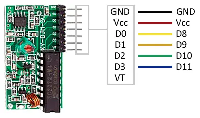
Logically, it is not mandatory to connect all 4 channels, we will only connect the digital signals that we need. The connection, as seen from Arduino, would be the following.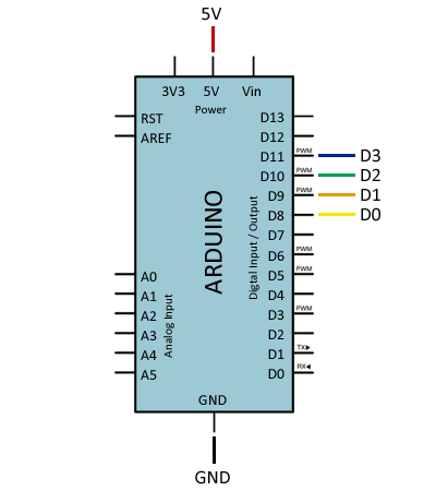
In the transmitter control, we do not have to take any action. We only need to make sure it has batteries.
Code examples
The necessary code is also quite simple. The receiver is responsible for converting the signals from the control into an active digital signal while the corresponding channel button is pressed.
Therefore, we only have to read the state of each pin of the receiver with the [digital input].(/en/digital-inputs-arduino/)
// D0 - 8
// D1 - 9
// D2 - 10
// D3 - 11

const int pinB = 8;
const int pinD = 9;
const int pinA = 10;
const int pinC = 11;

void setup()
{
  Serial.begin(9600);
}

void loop()
{
  if (digitalRead(pinA) == HIGH)
  {
    Serial.println("A");
    delay(1500);
  }

  if (digitalRead(pinB) == HIGH)
  {
    Serial.println("B");
    delay(1500);
  }

  if (digitalRead(pinC) == HIGH)
  {
    Serial.println("C");
    delay(1500);
  }

  if (digitalRead(pinD) == HIGH)
  {
    Serial.println("D");
    delay(1500);
  }
  delay(10);
Download the code
All the code from this post is available for download on Github. 
