What is an active buzzer?
Active buzzers, sometimes called buzzers, are devices that generate a sound of a specific and fixed frequency when connected to voltage.
An active buzzer incorporates a simple oscillator so that only a current supply to the device is necessary for it to emit sound. In contrast, passive buzzers need to receive a wave of a certain frequency.
By internally incorporating the necessary electronics to make the speaker vibrate, an active buzzer is very easy to connect and control. In addition, it does not put a load on the processor since it does not have to generate the electric wave that will become sound.
On the other hand, they have the disadvantage that we will not be able to change the tone of the emitted sound, so we will not be able to play melodies, something that we can do with passive buzzers.
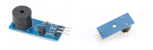
Physically, they can be very similar, or even identical, to passive buzzers, so it can be difficult to determine at a glance whether a buzzer is active or passive.
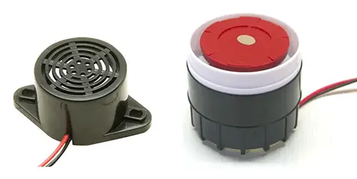
There are active buzzers in a wide range of sizes and powers, from almost imperceptible tones to really strident alarms. The electrical consumption, logically, also varies with the power of the buzzer.
We can use lower power active buzzers, for example, to give warnings to the user or provide feedback for some action, such as pressing a button, so that the user can verify that their action has been received.
For their part, higher power buzzers are suitable for generating alarms simply, for example, combined with a motion sensor, a water sensor, or a flame sensor, among others.
Price
There are a variety of active buzzers that we can use in our Arduino projects. For example, we can find boards with an active buzzer and the necessary electronics to make it work for €0.45, from international sellers on eBay and AliExpress.
Regarding active buzzers of higher power, we can find ones from 90 to 110 dB for €2 to €3.
In this case, we will need a power stage to be able to activate the power required by the buzzer.
Assembly diagram
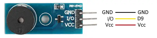
If we use a board with integrated electronics, the assembly is really simple, since the module itself incorporates the necessary components to provide the necessary current to the active buzzer.
Therefore, we simply power the module by connecting Vcc and GND to 5V and GND of Arduino, and finally
If we need to connect a higher power active buzzer, we must use a BJT transistor or MOSFET to amplify the current, or use a relay output.
For example, if we use a module with an IRF520N MOSFET, the assembly would be as follows.
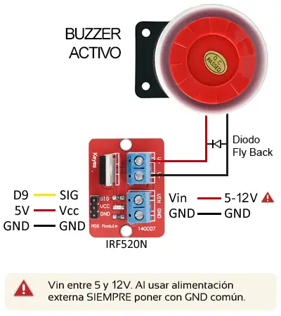
In both cases, the connection from Arduino is the same, as we only need to use a digital output to turn on the module.
Example assembly code
The necessary code is simple, since to control the buzzer we only need to use a digital output, as we saw in the digital outputs post.
For example, the following code would simply turn on and off the laser diode for 5 seconds, letting it rest for 20 seconds.
const int pin = 9;

void setup() {
  pinMode(pin, OUTPUT);  // define pin as output
}

void loop(){
  digitalWrite(pin, HIGH);   // set the pin to HIGH
  delay(5000);               // wait for 5 seconds
  digitalWrite(pin, LOW);    // set the pin to LOW
  delay(20000);               // wait for 20 seconds
}
In the next example, we want the buzzer to be activated as an alarm for a certain event. Let’s assume that we have a certain function GetSystemState() that performs the necessary sensor measurements and calculations to determine if the alarm needs to be turned on.
We simply call the function and turn on the alarm if necessary, keeping it on for a minimum of 5 seconds.
const int pin = 9;

bool isAlarmOn = 0;     // stores the state of the alarm

void setup() {
  pinMode(pin, OUTPUT);  // define pin as output
}

bool GetSystemState()
{
    return true;  // change depending on the sensor used
}

void loop(){
  isAlarmOn = GetSystemState();

  if(isAlarmOn)
  {
     digitalWrite(pin, HIGH);    // set the pin to HIGH
     delay(5000);               // wait for 5 seconds
  }
  else
  {
     digitalWrite(pin, LOW);    // set the pin to LOW
  }
  delay(1000);
}
Download the code
All the code from this post is available for download on Github. 
