In the previous post, we intensively covered the EMA exponential filter applied to low-pass and high-pass filtering. In this post, we will delve deeper into the topic and extend it to band-pass and band-stop filters.
To recap, remember that a signal can be considered as a sum of frequency components. An ideal low-pass filter (which is impossible to achieve in the real world) would allow components below a cutoff frequency (Fc) to pass. On the other hand, an ideal high-pass filter would allow components above a cutoff frequency to pass.
Band-pass and band-stop filters require two cutoff frequencies, which we will generically call the lower cutoff frequency (Fci) and the upper cutoff frequency (Fcs).
An ideal band-pass filter only allows frequencies above the lower cutoff and below the upper cutoff to pass, i.e., the frequency components within a band between both cutoff frequencies (Fci to Fcs).
Band-pass filters have a wide range of applications in electronics. You use them daily every time you use a device that “tunes” a signal. This includes all forms of communication, from radio, television, mobile phones, Wi-Fi, among an almost infinite number of applications.
On the other hand, the band-stop filter is the opposite case, meaning it removes the components between both cutoff frequencies, thus only allowing frequencies from -∞ to Fci and from Fcs to +∞ to pass.
Although not as common, they also have a huge field of application when we want to eliminate a signal of known frequency. For example, we can eliminate alternating current frequencies, filter vibrations from a machine rotating at known revolutions, or remove flicker in optical sensors and cameras caused by artificial lights powered by alternating current.
Generating a Band-Pass and Band-Stop Filter
To generate a band-pass or band-stop filter, we usually start from a low-pass filter and obtain the others through operations with the original signal. The results would be analogous starting from a high-pass filter, but algorithms to directly generate a high-pass filter are much less common than those for low-pass.
Recall that if we had our imaginary (and by now almost famous) ideal low-pass filter, generating a high-pass filter would be as simple as subtracting the low-pass filter from the original signal.
To visualize it, imagine the signal’s spectrum with its frequency components from -∞ to +∞. The low-pass filter only allows frequencies below the cutoff frequency (Fc) to pass, i.e., frequencies from -∞ to Fc.
Therefore, subtracting the low-pass filter result from the spectrum leaves frequencies from Fc to +∞ to pass, which precisely corresponds to the behavior of a high-pass filter.
By extension, to generate a band-pass filter, we only need to subtract the low-pass filter of the lower frequency from the low-pass filter of the upper frequency.
The upper low-pass filter will leave frequencies from -∞ to Fcs, and the lower low-pass filter will leave frequencies from -∞ to Fci, so subtracting both values will leave frequencies from Fci to Fcs, which is exactly what we want.
Finally, to obtain the band-stop filter, we only need to subtract the band-pass filter from the original signal, which will allow frequencies from -∞ to Fci and Fcs to +∞ to pass.
At this point, it’s worth remembering that most of what is explained here applies to a wide variety of filters. In this post, we use the EMA exponential filter because it is widely used and achieves good results with a simple implementation and high computational efficiency.
However, any algorithm that “smooths” a signal can be used as a low-pass filter (with better or worse characteristics) and, therefore, is susceptible to giving rise to a high-pass, band-pass, and band-stop filter.
Band-Pass Filter Results
As we said in the previous post, in the exponential filter type, the amount of smoothing is controlled through the alpha factor. It is not easy to find a simple relationship with the cutoff frequency, among other things, because the sampling frequency is unknown and variable.
What we do know is that the lower the alpha factor, the greater the signal smoothing, and therefore, the lower the cutoff frequency. Remember that, as a downside, the delay between the filtered signal and the original signal will also be greater.
In a band-pass and band-stop filter, we will have two alpha factors which we will call Low and High, corresponding respectively to the lower and upper cutoff frequencies.
Next, we will see the effect of these factors with the band-pass filter results for different combinations of alpha Low and High applied to the same signal.
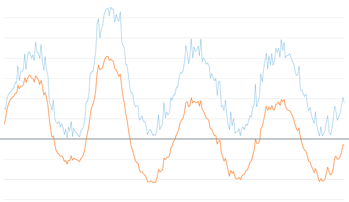
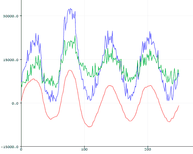
These are the results for an alpha Low of 0.025 and alpha High of 0.5. Note that the lower filter has eliminated the bias after a few oscillations, while the upper filter has smoothed some of the high-frequency noise.
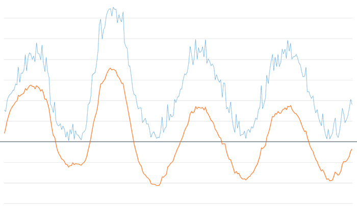
If we decrease the alpha high factor to 0.3, keeping low at 0.025, we see that most of the high-frequency noise is eliminated.
And if we decrease the alpha high factor even further to 0.15, we will see that we have eliminated all components except the fundamental harmonics of the example signal.
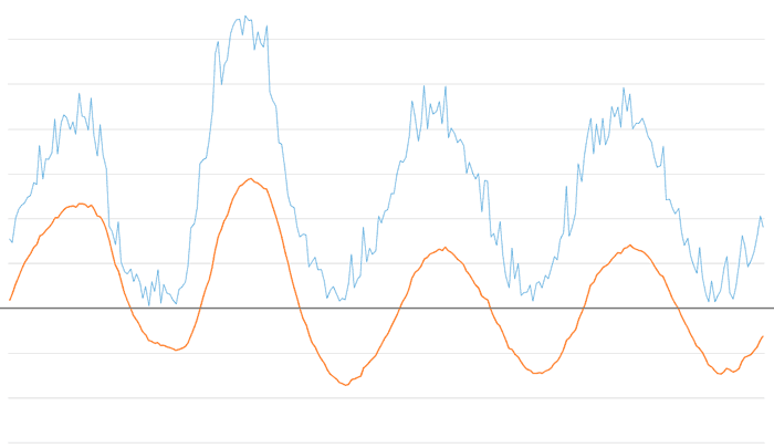
That is, in a single filter we have eliminated high-frequency noise and the signal bias. Not bad for such a simple filter, right?
Band-Pass and Band-Stop Filter in Arduino
Here is a simple implementation of an exponential band-pass and band-stop filter (EMA). In the example, we will filter a series of unordered integers that simulate a signal like the one we might obtain when taking a measurement. We access these values through the GetMeasure() function, which simulates the data acquisition process.
The results are displayed via the serial port. If you use the Serial Plotter of the Standard IDE, you can easily see the results graphically.
float EMA_ALPHA_LOW = 0.025;
float EMA_ALPHA_HIGH = 0.1;
int EMA_LP_LOW = 0;
int EMA_LP_HIGH = 0;
int EMA_BP = 0;
int EMA_BS = 0;

int values[] = {7729, 7330, 10075, ... };
int valuesLength = sizeof(values) / sizeof(int);

int getMeasure()
{
  int static index = 0;
  index++;
  return values[index-1];
}

void setup()
{
  Serial.begin(115200);

  for (int iCount = 0; iCount < valuesLength; iCount++)
  {
    int value = getMeasure();
    int filteredBP = EMABandPassFilter(value);
    int filteredBS = EMABandStopFilter(value);
    Serial.print(value);
    Serial.print(",");
    Serial.print(filteredBP);
    Serial.print(",");
    Serial.println(filteredBS);
  }
}

void loop()
{
  delay(10000);
}

int EMABandPassFilter(int value)
{
  EMA_LP_LOW = EMA_ALPHA_LOW * value + (1 - EMA_ALPHA_LOW) * EMA_LP_LOW;
  EMA_LP_HIGH = EMA_ALPHA_HIGH * value + (1 - EMA_ALPHA_HIGH) * EMA_LP_HIGH;
  EMA_BP = EMA_LP_HIGH - EMA_LP_LOW;
  return EMA_BP;
}

int EMABandStopFilter(int value)
{
  EMA_LP_LOW = EMA_ALPHA_LOW * value + (1 - EMA_ALPHA_LOW) * EMA_LP_LOW;
  EMA_LP_HIGH = EMA_ALPHA_HIGH * value + (1 - EMA_ALPHA_HIGH) * EMA_LP_HIGH;
  EMA_BP = EMA_LP_HIGH - EMA_LP_LOW;
  EMA_BS = value - EMA_BP;
  return EMA_BS;
}
The results in the Serial Plotter of the Standard IDE will be as follows,
Band-Pass and Band-Stop Filter in a Library
What if we put it in a library to make it more convenient to use? Of course, here is a Double EMA Filter library for Arduino. Enjoy!
Download the Code
All the code from this post is available for download on Github. 
