What is an SCT-013 sensor?
The SCT-013 family consists of non-invasive current sensors that allow measuring the intensity that passes through a conductor without the need to cut or modify the conductor. These sensors can be used with a processor such as Arduino to measure the intensity or power consumed by a load.
The SCT-013 sensors are current transformers, instrumentation devices that provide a measurement proportional to the intensity that passes through a circuit. The measurement is carried out through electromagnetic induction.
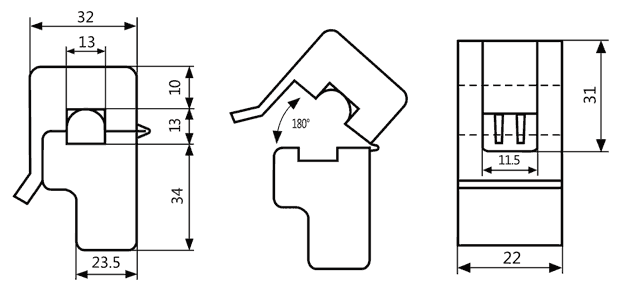
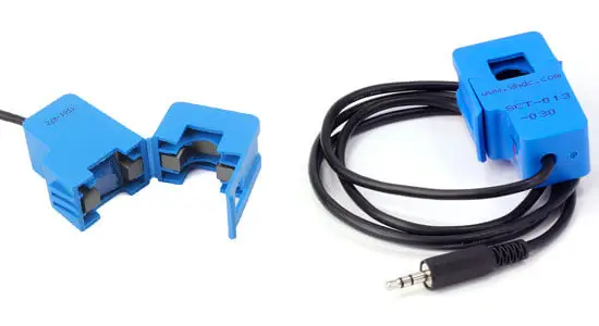
The SCT-013 sensors have a split ferromagnetic core (like a clamp) that allows it to be opened to wind a conductor of an electrical installation without the need to cut it.
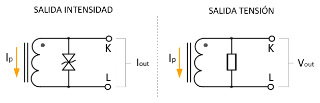
Within the SCT-013 family, there are models that provide the measurement as a current or voltage output. Whenever possible, it is preferable to use the voltage output because the connection is simpler.
The sensor’s accuracy can be 1-2%, but it is very important for the ferromagnetic core to close properly. Even a small gap of air can introduce deviations of 10%.
As a disadvantage, being an inductive load, the SCT-013 introduces a variation in the phase angle whose value is a function of the load passing through it, and can be up to 3º.
Current transformers are common components in the industrial world and in electrical distribution, allowing monitoring the consumption of consumption points where other types of measurement would be impossible. They are also part of multiple measurement instruments, even in portable equipment such as perimeter clamps or network analyzers.
In our electronics and home automation projects, we can use the SCT-013 current sensors, for example, to measure the electrical consumption of an appliance, check the status of an electrical installation, and are common components in home energy monitors to record the consumption of an installation or even access it through the internet in real time.
Price
There are various models within the SCT-013 family, which vary in the measurement range and in the form of the output. Physically they are identical, although it is possible to identify them by the text written on the housing.
The price of all of them is similar, they can be found for 4-4.50€, searching from international sellers on eBay or AliExpress.
The most frequent ones are the SCT-013-000 for a maximum current of 100A and an output of 50mA (100A:50mA), and the SCT-013-030 for maximum currents of 30A (30A/1V) and output in 1V voltage.
However, even though the SCT-013-000 is very common in online stores, as we have said, we will normally prefer the models with voltage output.
Finally, it is important to have a wide measurement range, but it should be taken into account that a model with a higher maximum intensity will result in less precision. An intensity of 30A at 230V corresponds to a load of 6,900W, which is sufficient for most domestic users.
How does an SCT-013 work?
The SCT-013 sensor family consists of small current transformers or CT (Current transformer). Current transformers are widely used as measuring elements.
A current transformer is similar to a voltage transformer and is based on the same operating principles (in fact, it is formally identical). However, they pursue different objectives and, consequently, are designed and built differently.
A current transformer seeks to generate a current in the secondary that is proportional to the current passing through the primary. To do this, it is desired that the primary is formed by a reduced number of turns.
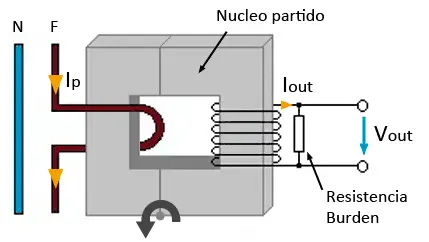
We can use this to build a non-invasive current sensor. In a current sensor, the ferromagnetic core can be divided so that it can be opened and wound around a conductor.
In this way, we have a transformer in which:
- The cable through which the current to be measured flows constitutes a primary winding
- The “clamp” is the magnetic core
- The secondary winding is integrated as part of the probe.
When the alternating current flows through the conductor, a magnetic flux is generated in the ferromagnetic core, which in turn generates an electric current in the secondary winding.
The current transformation ratio depends on the ratio between the number of turns.
The primary is generally formed by a single turn formed by the conductor to be measured. Although it is possible to wind the conductor so that it passes more than once through the inside of the “clamp”. The number of turns of the secondary, integrated in the probe, varies between 1000-2000 according to SCT-013 models.
Unlike voltage transformers, in a current transformer, the secondary circuit should never be open, because the induced currents could damage the component. For this reason, the SCT-130 sensors have protections (burden resistance in voltage output sensors, or protection diodes in current output sensors).
Mounting Scheme
To understand the connection of the SCT-013 sensor, we have to understand and solve three problems,
- Sensor output in current
- Voltage range adaptation
- Positive and negative voltages
Sensor output in current
The SCT-013 are current transformers, that is, the measurement is obtained as a signal of intensity proportional to the current that flows through the cable. But processors are only capable of measuring voltages.
This problem is easy to solve. To convert the output in current to a voltage output, we only have to include a resistance (burden resistance).
Except for the SCT-013-100 model, all other models have an internal burden resistance so that the output is a 1V voltage signal. Therefore, we won’t even have to worry about it.
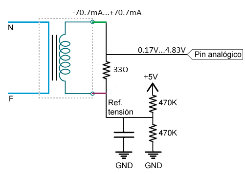
Only in the case of the SCT-013-100, it lacks internal burden resistance, so the output is a ±50mA signal. A 33Ω resistance in parallel with the sensor will be sufficient.
Positive and negative voltages
Another problem that we have to solve is that we are measuring alternating current, and the induced intensity in the secondary is also alternating. After passing through the burden resistance (internal or external), the voltage output is also alternating.
However, as we know, the analog inputs of most processors, including Arduino, can only measure positive voltages.
To measure the voltages of the transformer’s output, we have several options, from worst to best.
Rectify the signal using a diode bridge, and measure the wave as positive values. Not recommended because we lose the information about whether we are in the negative or positive half-cycle, also because we will have the voltage drop of the diode and, even worse, the diode does not conduct below a certain voltage so the signal will be distorted at the zero crossings.
Add a DC offset using two resistors and a capacitor that provide a midpoint between GND and Vcc. Much better if we also add an operational amplifier as a voltage follower.
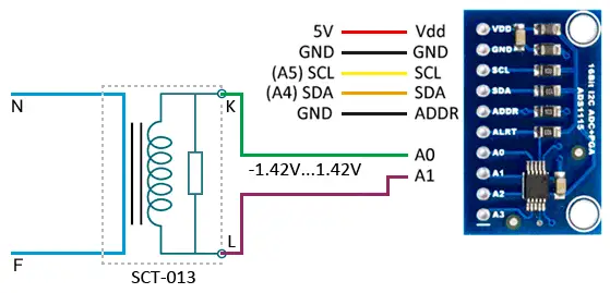
Add an ADC with differential input, which allows measurements of positive and negative voltages, such as the ADS1115. This is the option we are going to use.
Voltage range adaptation
The last problem is that we must adapt the voltage range at the sensor’s output. Arduino can only make measurements between 0 and Vcc. In addition, the smaller the range, the more precision we lose, so it is advisable to adjust to this range.
On the other hand, we must take into account that when talking about alternating current, RMS values are normally used. Let’s briefly remember the peak voltage and peak-to-peak equations.
Therefore, in the case of sensors with ±1V RMS output, the peak voltage will be ±1.414V, and the peak-to-peak voltage will be 2.828V.
In the case of the SCT-013-100, the output will be ±50mA. With an external burden resistance of 33Ω, the output voltage will be ±1.65V RMS, and therefore a peak voltage of ±2.33V and a peak-to-peak voltage of 4.66V.
Electrical Connection
We have all the components to measure grid intensity with an SCT-013 sensor. We are going to use a sensor with a ±1V RMS voltage output and internal burden resistance, together with an ADC like the ADS1115 in differential mode.
Adjusting the gain of the ADS1115 to 2.048V, we will be within the range of ±1.414V. In the case of a 30A sensor, we will have a precision of 1.87mA, and 6.25 mA for a 100A sensor.
If you use an SCT-013-100 with a ±50mA output, you will have to add an external burden resistance of 33Ω and increase the gain of the ADS1115 to 4.096V to comply with the ±2.33V range.
The connection, seen from Arduino, would only be the power supply of the ADS1115 module as we saw in the entry on the ADS1115.
To make the measurements, it is important that we only take one of the conductors with the “clamp”. If we take more than one conductor (two conductors in the case of single-phase installations, three in three-phase installations), the effect of the conductors would cancel each other out. This will generate a null induction and, therefore, a null measurement.
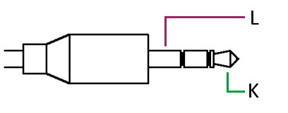
The SCT-013 sensors have a 3.5mm Jack connector, very common in audio, but not the most convenient to use in our electronic projects. To be able to connect it, we will have to either cut the cable, or acquire a female connector to which we will solder the cables. Fortunately, they are easy terminals to acquire, although you should not rule out cutting the cable either.
If you do not want to use an external ADC, you can use the most conventional solution, which is to add a circuit that allows us to add a central offset.
From now on, we will assume that you are using an Arduino with Vcc 5V. If you are using another processor or an Arduino model with a different Vcc (for example 3.3V), you will have to adjust the assembly accordingly.
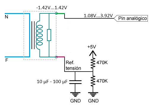
Where we have added a DC offset point of 2.5V, so the final range is from 1.08V to 3.92V, within the range of the analog inputs of an Arduino powered at 5V.
In the case of using the SCT-013-100 with a ±50mA output, you will have to add an external burden resistance of 33 Ohms and the final range will be from 0.17V to 0.483V, also within the range of the analog inputs of an Arduino at 5V.
Code Examples
Assembly with ADS1115
If you have used the assembly with an SCT-013 with a ±1V RMS output and ADS1115, the necessary code is similar to what we saw in the entry about the ADS1115. You will need the Adafruit library for the ADS1115.
To make the ADS1115 sample at a higher speed, we must modify the following line of the ‘Adafruit_ADS1015.h’ file
#define ADS1115_CONVERSIONDELAY (8)
To,
#define ADS1115_CONVERSIONDELAY (1)
With this, we will manage to reduce the sampling time from about 8-9 ms (about 100 Hz) to approximately 1.8 ms (about 500 Hz). With this, we move away from the Nyquist frequency, and improve the behavior of the measurement.
#include <Wire.h>
#include <Adafruit_ADS1015.h>

Adafruit_ADS1115 ads;

const float FACTOR = 30; //30A/1V

const float multiplier = 0.0625F;

void setup()
{
  Serial.begin(9600);

  ads.setGain(GAIN_TWO);        // ±2.048V  1 bit = 0.0625mV
  ads.begin();
}

void printMeasure(String prefix, float value, String postfix)
{
 Serial.print(prefix);
 Serial.print(value, 3);
 Serial.println(postfix);
}

void loop()
{
 float currentRMS = getCorriente();
 float power = 230.0 * currentRMS;

 printMeasure("Irms: ", currentRMS, "A ,");
 printMeasure("Potencia: ", power, "W");
 delay(1000);
}

float getCorriente()
{
 float voltage;
 float corriente;
 float sum = 0;
 long tiempo = millis();
 int counter = 0;

 while (millis() - tiempo < 1000)
 {
   voltage = ads.readADC_Differential_0_1() * multiplier;
   corriente = voltage * FACTOR;
   corriente /= 1000.0;

   sum += sq(corriente);
   counter = counter + 1;
  }

 corriente = sqrt(sum / counter);
 return(corriente);
}
Another version is to use the maximum and minimum of the measurement, and calculate the measurement from the peak value. The results should be similar to those seen in the example with the squared sum. For this, you can replace the function with the following.
float getCorriente()
{
 long tiempo = millis();
 long rawAdc = ads.readADC_Differential_0_1();
 long minRaw = rawAdc;
 long maxRaw = rawAdc;
 while (millis() - tiempo < 1000)
 {
   rawAdc = ads.readADC_Differential_0_1();
   maxRaw = maxRaw > rawAdc ? maxRaw : rawAdc;
   minRaw = minRaw < rawAdc ? minRaw : rawAdc;
 }

  maxRaw = maxRaw > -minRaw ? maxRaw : -minRaw;
  float voltagePeak = maxRaw * multiplier / 1000;
  float voltageRMS = voltagePeak * 0.70710678118;
  float currentRMS = voltageRMS * FACTOR;
  return(currentRMS);
}
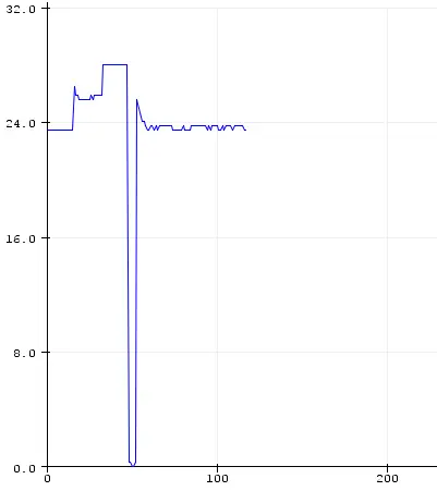
We can see the results in the serial port monitor, graph it with the serial plotter, or collect it in a larger project to display it on a web page, or record it on an SD card.
Assembly with resistors and midpoint
In this case, the example is very simple, we only have to make the measurement using an analog input.
const float FACTOR = 30; //30A/1V

const float VMIN = 1.08;
const float VMAX = 3.92;

const float ADCV = 5.0;  //For Vcc
//const float ADCV = 1.1; //For internal reference

void setup()
{
  Serial.begin(9600);
  //analogReference(INTERNAL);
}

void printMeasure(String prefix, float value, String postfix)
{
  Serial.print(prefix);
  Serial.print(value, 3);
  Serial.println(postfix);
}

void loop()
{
  float currentRMS = getCorriente();
  float power = 230.0 * currentRMS;

  printMeasure("Irms: ", currentRMS, "A ,");
  printMeasure("Potencia: ", power, "W");
  delay(1000);
}

float getCorriente()
{
  float voltage;
  float corriente;
  float sum = 0;
  long tiempo = millis();
  int counter = 0;

  while (millis() - tiempo < 500)
  {
    voltage = analogRead(A0) * ADCV / 1023.0;
    corriente = fmap(voltage, VMIN, VMAX, -FACTOR, FACTOR);

    sum += sq(corriente);
    counter = counter + 1;
    delay(1);
  }

  corriente = sqrt(sum / counter);
  return(corriente);
}

// scale change between floats
float fmap(float x, float in_min, float in_max, float out_min, float out_max)
{
 return (x - in_min) * (out_max - out_min) / (in_max - in_min) + out_min;
}
Download the Code
All the code from this post is available for download on Github. 
