What is an L298N?
The L298N is a motor controller that allows you to turn on and control two DC motors from Arduino, varying both the direction and speed of rotation.
As we frequently mention, Arduino and, in general, all automatons do not have enough power to move actuators. In fact, the function of a processor should not be to execute actions, but to send actions to drivers that do the “heavy lifting.”
The L298N can also control a single stepper motor, although, in general, we will prefer to use devices specifically designed for stepper motors.
The maximum current that the L298N can supply to the motors is, in theory, 2A per output (up to 3A peak) and a supply voltage of 3V to 35V.
However, the L298N has low efficiency. The electronics result in a voltage drop of about 3V, which means that the voltage received by the motor is about 3V lower than the supply voltage.
These losses are dissipated in the form of heat, which means that, in practical terms, it is difficult for us to obtain more than 0.8-1A per phase without exceeding the operating temperature range.
The L298N incorporates protections against effects that can occur when handling DC motors. It has protections against overcurrent, over-temperature, and protection diodes against induced currents (flyback).
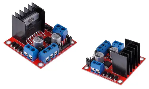
The L298N controller is widely used in electronic and robotics projects due to its simplicity of use, low cost, and good value for money.
Price
The L298N controller is an inexpensive component, and we can find it for €1.40 from international sellers on AliExpress or eBay.
How does an L298N work?
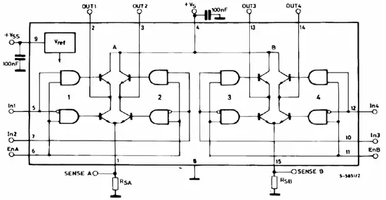
Basically, an L298N consists of two H-bridges, one for output A and another for output B.
An H-bridge is a component widely used in electronics to power a load in a way that we can reverse the direction of the current that passes through it.
Internally, an H-bridge is a formation of 4 transistors, connected between Vcc and GND, with the load to be powered between them. Drawn in a diagram, the assembly has the shape of an “H,” from which it gets its name.
By acting on the 4 transistors, activating the diagonally opposite transistors of each branch, we can vary the direction in which the current passes through the load.
By simultaneously connecting the upper or lower transistors, we can put the load to Vcc or Gnd, respectively, a configuration that we will use as a brake.
Finally, we should never turn on both transistors of the same branch (left or right), as we will be causing a short circuit between Vcc and GND.
The L298N board incorporates electronics that simplify the connection to the H-bridge, grouping the connections in 3 accessible pins (for each output) and eliminating the possibility of generating a short circuit.
Two of these pins, IN1 and IN2 (IN3 and IN4 for output B), control the activation of the transistors of each of the two branches, turning on the upper or lower branch of the same.
The third pin (IEA/IEB) simultaneously deactivates all the transistors of the H-bridge, disconnecting the load completely.
Setup Diagram
The L298N connection board incorporates a voltage input, a series of jumpers to configure the module, two outputs A and B, and the input pins that regulate the speed and direction of rotation.
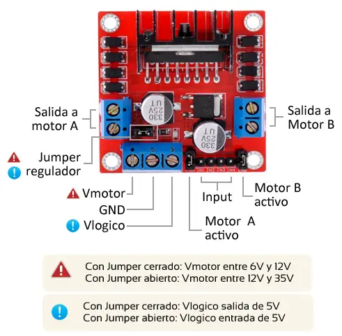
The voltage input provides the voltage that will power the motors. The acceptable input range is from 3V to 35V and is supplied through the 2 left terminals of the input connection terminal.
The third terminal of the input connection terminal, Vlógico, is connected to the L298N electronics and needs to have a value between 4.5 and 5.5V for the board to function correctly.
For this reason, the module incorporates a voltage regulator that supplies the necessary voltage at Vlógico. This regulator can be deactivated by removing the jumper from the board. We will deactivate the regulator when the supply voltage is less than 5V or more than 15V.
Therefore:
- If the regulator is activated (closed jumper), Vlógico is a 5V output that we can use to power other devices.
- If the regulator is deactivated (open jumper), Vlógico is an input to which we will have to provide a voltage of 4.5 to 5.5V.
We should not introduce current into Vlógico with the regulator activated (jumper connected) or we can damage the module.
On the other hand, we have the two A and B connection terminals that supply the output to the motors.
Finally, we have the input pins that control the direction and speed of rotation.
- The pins IEA, IN1, and IN2 control output A.
- The pins IEB, IN3, and IN4 control output B.
The pins IN1, IN2, and IN3, and IN4 control the forward and reverse direction of rotation, respectively, of outputs A and B.
The pins IEA and IEB deactivate the output. We can connect them permanently using a jumper, or connect a PWM signal to control the speed of rotation.
If we want to use both phases, and be able to choose both the direction of rotation and the speed, and power from a 12V source, the connection diagram to Arduino would be as follows.
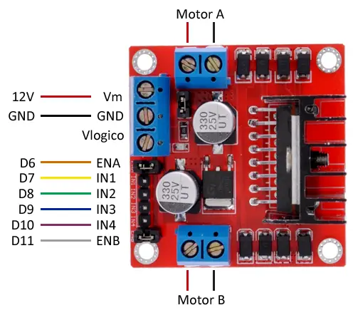
While the connection, seen from the Arduino side, would be the following.
The power supply of Arduino in this case could be done from the 12V source to the Vin pin of Arduino (using the voltage regulator of Arduino), or from the Vlogico pin of the L298N to the 5V pin of Arduino (using the L298N regulator).
Whenever you use more than one voltage source remember to connect all the GNDs including that of Arduino. Otherwise, you can damage a component.
Code Examples
To control the two motors, we must correctly activate the digital outputs connected to pins IN1 and IN2 (output A), or pins IN3 and IN4 (output B).
The possible combinations are:
| Forward | Backward | Brake | |
|---|---|---|---|
| IN1 (or IN3) | HIGH | LOW | LOW |
| IN2 (or IN4) | LOW | HIGH | LOW |
Regarding the pins IEA and IEB, we will use a PWM output to control the speed of rotation.
The following code moves the motor from output A forward at 80% speed.
const int pinENA = 6;
const int pinIN1 = 7;
const int pinIN2 = 8;

const int speed = 200;    //speed of rotation 80% (200/255)

void setup()
{
  pinMode(pinIN1, OUTPUT);
  pinMode(pinIN2, OUTPUT);
  pinMode(pinENA, OUTPUT);
}

void loop()
{
  digitalWrite(pinIN1, HIGH);
  digitalWrite(pinIN2, LOW);
  analogWrite(pinENA, speed);
  delay(1000);
}
The code needed to control the L298N is not complicated, but if we are not organized, it can quickly grow in size, which will be a problem when integrating it into larger projects, such as vehicles or robots.
Therefore, it is convenient to group and reuse the code in functions that simplify its use.
The following code turns on both motors in one direction, then in the opposite direction, and finally stops them completely, and then starts the cycle again.
const int pinENA = 6;
const int pinIN1 = 7;
const int pinIN2 = 8;
const int pinIN3 = 9;
const int pinIN4 = 10;
const int pinENB = 11;

const int waitTime = 2000;  //wait time between phases
const int speed = 200;    //speed of rotation

const int pinMotorA[3] = { pinENA, pinIN1, pinIN2 };
const int pinMotorB[3] = { pinENB, pinIN3, pinIN4 };

void setup()
{
  pinMode(pinIN1, OUTPUT);
  pinMode(pinIN2, OUTPUT);
  pinMode(pinENA, OUTPUT);
  pinMode(pinIN3, OUTPUT);
  pinMode(pinIN4, OUTPUT);
  pinMode(pinENB, OUTPUT);
}

void loop()
{
  moveForward(pinMotorA, 180);
  moveForward(pinMotorB, 180);
  delay(waitTime);

  moveBackward(pinMotorA, 180);
  moveBackward(pinMotorB, 180);
  delay(waitTime);

  fullStop(pinMotorA);
  fullStop(pinMotorB);
  delay(waitTime);
}

void moveForward(const int pinMotor[3], int speed)
{
  digitalWrite(pinMotor[1], HIGH);
  digitalWrite(pinMotor[2], LOW);

  analogWrite(pinMotor[0], speed);
}

void moveBackward(const int pinMotor[3], int speed)
{
  digitalWrite(pinMotor[1], LOW);
  digitalWrite(pinMotor[2], HIGH);

  analogWrite(pinMotor[0], speed);
}

void fullStop(const int pinMotor[3])
{
  digitalWrite(pinMotor[1], LOW);
  digitalWrite(pinMotor[2], LOW);

  analogWrite(pinMotor[0], 0);
}
As we can see, with the functions we have created, it is easy to move a robot forward and backward, and it is even easy to use them to make it turn or follow paths. In a complex project, similar functions would be integrated within our object model.
We will use the L298N motor controller frequently in our projects, and soon we will see some projects like robots or vehicles that make use of the L298N.
Download the Code
All the code from this post is available for download on Github. 
