We have been discussing for a few posts how to reduce noise in measurements using multiple sampling and applying filters like the moving average filter.
In this post, we are going to look at the EMA (Exponential Moving Average) filter. The EMA exponential filtering is one of the most used in digital electronics due to its good results combined with an incredibly simple and efficient implementation.
The EMA filter consists of obtaining a filtered value from a measurement by applying the following expression
Where An is the filtered value, An-1 is the previous filtered value, M is the sampled value of the signal to be filtered, and alpha is a factor between 0 and 1.
Therefore, the EMA filter presents an input of “new” information through the measurement M, and a smoothing effect based on the memory provided by the previous filtered value An-1. The result of an EMA exponential filter is a smoothed signal where the amount of smoothing depends on the alpha factor, as we will analyze later.
The advantages in terms of simplicity and computational efficiency are evident. The calculation requires only a single simple instruction. In terms of memory requirements, we only need to store the previous filtered value. This represents a great computational advantage over other filters that require storing N values and performing calculations on all of them.
Low-Pass Filter
Like all filters that smooth a signal (it is not exclusive to the EMA filter) we can use the exponential filter as a low-pass filter, that is, an algorithm that (ideally) passes frequency components below a cutoff frequency.
We can use the low-pass filter to eliminate high-frequency noise superimposed on the signal, which we can use to improve sensor measurements and communications, among other uses.
Unfortunately, no real filter is perfect and the filters we can generate in reality have limitations that move them away from ideal behavior.
Furthermore, even if we could generate an ideal filter, it would not mean we could completely eliminate noise, as certain frequencies may overlap with the frequencies of interest of the signal itself (the real variations of the signal).
High-Pass Filter
Although less common, it is also possible to obtain a high-pass filter, that is, to eliminate frequencies below a cutoff frequency.
A high-pass filter can serve, for example, to digitally remove the direct current component (bias) of a signal, slow variations compared to the frequency of interest, detection of abrupt changes in the signal, among others.
If we could build an ideal low-pass filter, to obtain the high-pass filter we only have to subtract the signal after the low-pass filter from the original signal.
Of course, in the real world it is also impossible to build an ideal high-pass filter. In the case (very frequent) of building the high-pass filter from a low-pass filter, the limitations we will obtain are the result of those of the low-pass filter used.
Influence of the Alpha Factor
The Alpha factor conditions the behavior of the exponential filter and is related to the cutoff frequency of the filter. However, a simple relationship is not always possible since it depends on the sampling time of our system, which, in principle, is unknown and possibly variable between cycles.
Quantitatively:
- An Alpha = 1 value provides the unfiltered signal, as it disregards the filtering effect provided by the previous measurement.
- An Alpha = 0 value causes the filtered value to always be 0, as it disregards the new information that the measurement brings to the system.
Decreasing the Alpha factor increases the smoothing of the signal, but at the cost of also introducing negative consequences. On one hand, we can eliminate frequency components that were actually of interest to us, classifying as noise something that was actually a real variation of the signal.
On the other hand, decreasing the Alpha factor increases the system’s response time, that is, the time it takes for the system to stabilize to a constant input. This translates into the introduction of a delay between the original signal and the filtered signal.
Logically, the appropriate Alpha value will depend on the characteristics of our system, the sampled signal, and the noise we want to eliminate. In principle, we must adjust the value so that it is suitable for our setup, with common values being 0.2-0.6.
Low-Pass and High-Pass Filter Results
To illustrate the variation in the behavior of the low-pass and high-pass filter, let’s see the effect for different Alpha values on the same simulated signal. The signal has a main sinusoidal component and superimposed noise of different frequencies.
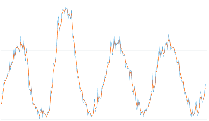
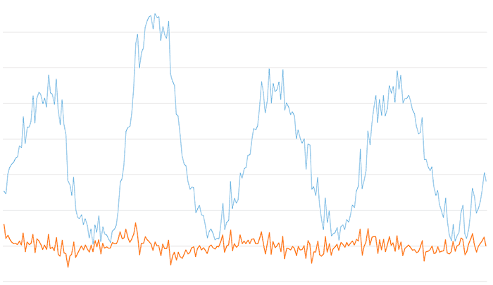
Here is the result of the low-pass filter for an Alpha value of 0.6 (a fairly common value in the real world). We see that part of the high-frequency noise has been eliminated, and most of the signal has been preserved.
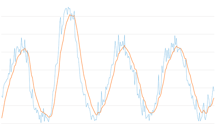
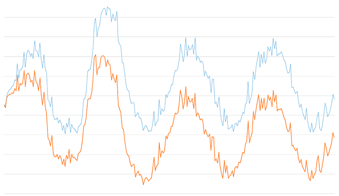
The result of the low-pass filter for a value of 0.2. The smoothing has increased and we have eliminated all high-frequency noise. On the other hand, the delay of the filtered signal is starting to become evident.
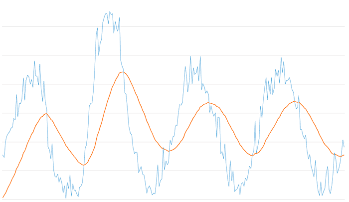
And the result of the low-pass filter for a low value of 0.05. All components of the signal except the main one have been eliminated, but in return we have a very significant delay in the filtered signal.
Regarding the high-pass filter, here is the result for the high-pass filter for an Alpha value of 0.6. We see that the low-frequency components of the signal are eliminated, leaving the faster variations, which appear centered on the Y0 axis.
And here the result of the high-pass filter for an Alpha value of 0.025. We observe that the shape of the original signal is preserved, but after a certain transient, the bias of the signal has been completely eliminated, which now appears centered at the origin.
As you can see, we have a great variety of behaviors with the same filter and it leads to very interesting results, from signal smoothing and high-frequency noise filtering with the low-pass filter, to bias elimination or obtaining main frequencies with the high-pass filter.
Why does the EMA filter work?
It is common to find literature and projects where exponential EMA filtering is used. What is not so common to find is an explanation of why an EMA filter works.
So why is this simple operation capable of filtering the noise of a signal?
Attention, next comes a section with “dense” mathematical demonstrations. If you don’t like math, or don’t feel like racking your brain right now, you can skip to the next section.

In reality, the EMA exponential filter is a particular case of a weighted average, that is, an average calculation in which each of the elements Xi has a factor Wi that weights its effect on the overall average calculation.
How is it that the formulation we saw earlier for the EMA filter can be deduced from a particular case of a weighted average?
Let’s start from a generic expression to obtain a series of filtered values Ai from a series of measurements Mi, subject to two parameters alpha and beta.
Analyzing what happens when using this expression on the measurement series
Generalizing we can write,
Therefore, the next filtered value is the sum of all previous measurements weighted by an exponential factor beta (which gives the filter its name) and scaled by a factor alpha.
The theory indicates that the average calculates the effect of all previous measurements, although the factor beta^n makes their effect reduced. However, in the real world, due to rounding, the contribution of the terms is null after a few iterations.
Where do the restrictions that both alpha and beta must be less than 1, and that both added together must equal 1, come from? Well, I suppose at this point saying that because it seems intuitive doesn’t satisfy you, does it? Since I’m already in the thick of it, let’s go all the way.
First, since the filtered value is obtained from a geometric series, it follows that, unless all measurements are equal to 0, any beta factor greater than 1 will cause the overall signal to quickly feed back and tend to infinity.
On the other hand, negative beta values would produce oscillating solutions. Therefore, it is deduced that to obtain stability, beta must be between 0 and 1.
To check the relationship between alpha and beta, suppose as a simplification that we introduce a constant value C as input. It is reasonable to expect that the filtered value obtained is also C. (what kind of filter would it be if we constantly input, for example, 10, and it gave us 8, or 12, right?)
With B < 1 the above expression simplifies to
Which finally reduces to,
Thus, the restrictions on alpha and beta are explained. You could also have accepted the answer that from the point of view of a variational formulation of the problem, the restrictions on alpha and beta allow for the invariant of the energy functional. But hey! You preferred the demonstration with series.
With this, we have demonstrated that the general expression of the EMA filter is actually a weighted average whose weighting factors follow an exponential progression with parameter beta, and that it is necessary for beta to be greater than or equal to 0 and less than 1 for the system to be stable.
Low-Pass and High-Pass Filter on Arduino
Here is a simple implementation of an exponential low-pass and high-pass filter (EMA). In the example, we are going to filter a series of unordered integers that simulate a signal like the one we might obtain when taking a measurement. We access these values through the GetMeasure() function, which simulates the data acquisition process.
The results are displayed on the serial port. If you use the Serial Plotter of the Standard IDE, you will be able to see the results graphically in a simple way.
float EMA_ALPHA = 0.6;
int EMA_LP = 0;
int EMA_HP = 0;

int values[] = { 7729, 7330, 10075, 10998, 11502, 11781, 12413, 12530, 14070, 13789, 18186, 14401, 16691, 16654, 17424, 21104, 17230, 20656, 21584, 21297, 19986, 20808, 19455, 24029, 21455, 21350, 19854, 23476, 19349, 16996, 20546, 17187, 15548, 9179, 8586, 7095, 9718, 5148, 4047, 3873, 4398, 2989, 3848, 2916, 1142, 2427, 250, 2995, 1918, 4297, 617, 2715, 1662, 1621, 960, 500, 2114, 2354, 2900, 4878, 8972, 9460, 11283, 16147, 16617, 16778, 18711, 22036, 28432, 29756, 24944, 27199, 27760, 30706, 31671, 32185, 32290, 30470, 32616, 32075, 32210, 28822, 30823, 29632, 29157, 31585, 24133, 23245, 22516, 18513, 18330, 15450, 12685, 11451, 11280, 9116, 7975, 8263, 8203, 4641, 5232, 5724, 4347, 4319, 3045, 1099, 2035, 2411, 1727, 852, 1134, 966, 2838, 6033, 2319, 3294, 3587, 9076, 5194, 6725, 6032, 6444, 10293, 9507, 10881, 11036, 12789, 12813, 14893, 16465, 16336, 16854, 19249, 23126, 21461, 18657, 20474, 24871, 20046, 22832, 21681, 21978, 23053, 20569, 24801, 19045, 20092, 19470, 18446, 18851, 18210, 15078, 16309, 15055, 14427, 15074, 10776, 14319, 14183, 7984, 8344, 7071, 9675, 5985, 3679, 2321, 6757, 3291, 5003, 1401, 1724, 1857, 2605, 803, 2742, 2971, 2306, 3722, 3332, 4427, 5762, 5383, 7692, 8436, 13660, 8018, 9303, 10626, 16171, 14163, 17161, 19214, 21171, 17274, 20616, 18281, 21171, 18220, 19315, 22558, 21393, 22431, 20186, 24619, 21997, 23938, 20029, 20694, 20648, 21173, 20377, 19147, 18578, 16839, 15735, 15907, 18059, 12111, 12178, 11201, 10577, 11160, 8485, 7065, 7852, 5865, 4856, 3955, 6803, 3444, 1616, 717, 3105, 704, 1473, 1948, 4534, 5800, 1757, 1038, 2435, 4677, 8155, 6870, 4611, 5372, 6304, 7868, 10336, 9091 };
int valuesLength = sizeof(values) / sizeof(int);

int getMeasure()
{
  static int index = 0;
  index++;
  return values[index - 1];
}

void setup()
{
  Serial.begin(115200);

  for (int iCount = 0; iCount < valuesLength; iCount++)
  {
    int value = getMeasure();
    int filteredLP = EMALowPassFilter(value);
    int filteredHP = EMAHighPassFilter(value);
    Serial.print(value);
    Serial.print(",");
    Serial.print(filteredLP);
    Serial.print(",");
    Serial.println(filteredHP);
  }
}

void loop()
{
  delay(10000);
}

int EMALowPassFilter(int value)
{
  EMA_LP = EMA_ALPHA * value + (1 - EMA_ALPHA) * EMA_LP;
  return EMA_LP;
}

int EMAHighPassFilter(int value)
{
  EMA_LP = EMA_ALPHA * value + (1 - EMA_ALPHA) * EMA_LP;
  EMA_HP = value - EMA_LP;

  return EMA_HP;
}
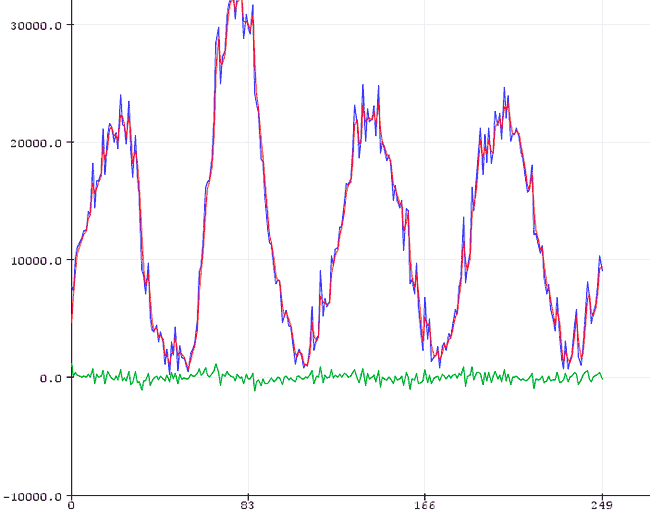
The results in the Serial Plotter of the Standard IDE will be as follows,
Low-Pass and High-Pass Filter in a Library
What if we put it in a library to make it more convenient to use? Of course, here is a Single EMA Filter library for Arduino. Enjoy it!
Download the Code
All the code from this post
