In this post, we will look at the I2C bus, one of the communication systems available in Arduino. In previous posts, we have already seen the serial port and the SPI bus, which together with the I2C bus, integrate the main communication systems.
The I2C bus is interesting because, similarly to the SPI bus, a large number of devices have I2C connectivity, such as accelerometers, compasses, displays, etc.
I2C is also called TWI (Two Wired Interface) solely for licensing reasons.
However, the patent expired in 2006, so there is currently no restriction on the use of the term I2C.
The I2C Bus
The I2C standard (Inter-Integrated Circuit) was developed by Philips in 1982 for internal communication of electronic devices in their products.
It was later progressively adopted by other manufacturers until it became a market standard.
The I2C bus requires only two wires for its operation,
CLKfor the clock signalSDAfor data transmission
This is an advantage over the SPI bus. On the other hand, its operation is a bit more complex, as is the electronics needed to implement it.
In the bus, each device has an address, which is used to access devices individually.
In general, each device connected to the bus must have a unique address. If we have several similar devices, we will have to change the address or, if not possible, implement a secondary bus.
In some devices, this address can be changed either by software or by hardware (in which case, frequently, the last 3 bits can be modified via jumpers or switches).
The I2C bus has a master-follower architecture. The master device initiates communication with the followers and can send or receive data from them. Followers cannot initiate communication (the master has to ask them first), nor can they talk directly to each other.
It is possible to have more than one master, but only one can be the master at a time. Changing masters involves high complexity, so it is not a frequent practice.
On the other hand, the I2C bus is synchronous. The master provides a clock signal, which keeps all devices on the bus synchronized.
This eliminates the need for each device to have its own clock, to agree on a transmission speed, and mechanisms to keep the transmission synchronized (as in UART).
Finally, the I2C protocol provides for Pull-UP resistors of the lines to Vcc. In Arduino, you will often see that these resistors are not installed, as the Wire library activates the internal Pull-UP resistors. However, the internal resistors have a value between 20-30kOhms, making them very weak Pull-UP resistors.
Using weak resistors implies that the rising edges of the signal will be slower, which means we can use lower speeds and shorter communication distances. If we want to use higher transmission speeds or distances, we must physically place Pull-UP resistors between 1k to 4K7.
I2C Bus Operation
To enable communication with only one data wire, the I2C bus uses a broad frame (the format of the sent data). Communication consists of:
- 7 bits for the address of the follower device we want to communicate with.
- One remaining bit indicates whether we want to send or receive information.
- A validation bit
- One or more bytes are the data sent to or received from the follower.
- A validation bit
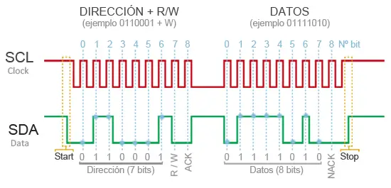
With these 7 address bits, it is possible to access 112 devices on the same bus (16 of the 128 possible addresses are reserved for special uses).
This increase in sent data (18 bits for every 8 bits of data) means that, in general, the speed of the I2C bus is low. The standard transmission speed is 100kHz, with a high-speed mode of 400kHz.
The I2C standard defines other operating modes, such as 8, 10, and 12-bit address transmission, or transmission speeds of 1Mbit/s, 3.4Mbit/s, and 5Mbit/s. They are not commonly used in Arduino.
Advantages and Disadvantages of I2C
Advantages
- Requires few wires
- Has mechanisms to verify that the signal has arrived
Disadvantages
- Its speed is medium-low
- It is not full duplex
- There is no verification that the message content is correct
The I2C Bus in Arduino
Arduino has hardware I2C support physically linked to certain pins. It is also possible to use any other group of pins as an I2C bus via software, but in that case, the speed will be much lower.
The pins to which it is associated vary from one model to another. The following table shows the arrangement in some of the main models. For other models, consult the corresponding pinout diagram.
| MODEL | SDA | SCK |
|---|---|---|
| Uno | A4 | A5 |
| Nano | A4 | A5 |
| Mini Pro | A4 | A5 |
| Mega | 20 | 21 |
To use the I2C bus in Arduino, the Standard IDE provides the “Wire.h” library, which contains the necessary functions to control the integrated hardware.
Some of the basic functions are as follows:
Wire.begin()  // Initializes the bus hardware
Wire.beginTransmission(address); // Begins the transmission
Wire.endTransmission(); // Ends the transmission
Wire.requestFrom(address,nBytes);  // requests a number of bytes from the follower at address
Wire.available();  // Detects if there are pending data to be read
Wire.write();  // Sends a byte
Wire.read();   // Receives a byte

Wire.onReceive(handler); // Registers a callback function upon receiving data
Wire.onRequest(handler); // Registers a callback function upon requesting dataThere are other more advanced libraries than Wire.h for handling the I2C bus, such as I2Cdevlib or I2C library.
I2C Scanner
In an ideal world, we would know the address of the device we buy. But sometimes, especially when buying from Chinese sellers, the manufacturer does not provide us with the device address or even provides it incorrectly.
This is a common and not at all worrying circumstance. For that, we have a sketch called “I2C Scanner” that scans all possible addresses on the bus and shows the result if it finds a device at an address.
This way we can comfortably determine the addresses of unknown devices.
The I2C scanner sketch is available at this link, or you can use the following reduced and translated version.
#include "Wire.h"

extern "C" {
    #include "utility/twi.h"
}

void scanI2CBus(byte from_addr, byte to_addr, void(*callback)(byte address, byte result) )
{
  byte rc;
  byte data = 0;
  for( byte addr = from_addr; addr <= to_addr; addr++ ) {
    rc = twi_writeTo(addr, &data, 0, 1, 0);
    callback( addr, rc );
  }
}

void scanFunc( byte addr, byte result ) {
  Serial.print("addr: ");
  Serial.print(addr,DEC);
  Serial.print( (result==0) ? " Found!":"       ");
  Serial.print( (addr%4) ? "\t":"\n");
}

const byte start_address = 8;
const byte end_address = 119;

void setup()
{
    Wire.begin();

    Serial.begin(9600);
    Serial.print("Scanning I2C bus...");
    scanI2CBus( start_address, end_address, scanFunc );
    Serial.println("\nFinished");
}

void loop()
{
    delay(1000);
}In a future post, we will see how to connect two Arduino boards via I2C bus, and how to connect an Arduino board with a Raspberry PI.
Download the Code
All the code from this post is available for download on Github.

