What is an MPU-6050 IMU?
The MPU-6050 is a six-degree-of-freedom (6DOF) inertial measurement unit (IMU) manufactured by Invensense, which combines a 3-axis accelerometer and a 3-axis gyroscope.
Communication can be done via both SPI and I2C bus, making it easy to obtain the measured data. The voltage supply is low, between 2.4 to 3.6V.
They are frequently integrated into modules such as the GY-521 that incorporate the necessary electronics to connect it easily to an Arduino. In most modules, this includes a voltage regulator that allows direct power supply to 5V.
It has 16-bit analog-to-digital converters (ADC). The accelerometer range can be adjusted to ±2g, ±4g, ±8g, and ±16g, and the gyroscope range to ±250, ±500, ±1000, and ±2000°/sec.
It is a sensor that consumes 3.5mA, with all sensors and the DMP activated. It has an embedded temperature sensor, a high-precision clock, and programmable interruptions. It can also be connected to other I2C devices as a leader.
The MPU-6050 incorporates an internal processor (DMP Digital Motion Processor) that executes complex MotionFusion algorithms to combine the measurements of the internal sensors, avoiding the need to perform the filters externally.
The MPU-6050 is one of the most widely used IMUs due to its high quality and price. It will be one of the components that we will most frequently incorporate into our electronic and robotic projects.
If you want to learn more about accelerometers, gyroscopes, and IMUs in Arduino, see the series of posts How to use an accelerometer with Arduino, How to use a gyroscope with Arduino, and Measuring tilt with IMU.
Price
The MPU-6050 is an excellent sensor in terms of price due, among other factors, to its wide usage, which has allowed its price to be reduced.
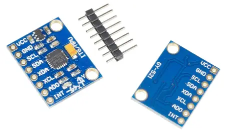
It can be found on mounting boards such as the GY-521, which incorporates the necessary electronics to connect it easily to an Arduino, for €1.10 from international sellers on eBay or AliExpress.
Connection Diagram
The connection is simple, simply power the module from Arduino using GND and 5V and connect the SDA and SCL pins of Arduino to the corresponding pins of the sensor.
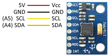
While the connection seen from the Arduino side would be as follows.
In Arduino Uno, Nano, and Mini Pro, SDA is pin A4 and SCK is pin A5. For other models of Arduino, see the corresponding pinout diagram.
Verify that your board is compatible with 5V before connecting it to Arduino. If not, you will have to use a logic level adapter.
Code Examples
To read the MPU-6050, we will use the library developed by Jeff Rowberg available at this link. We will also use the I2Cdev library developed by the same author, which improves I2C communication.
The library provides code examples, which is advisable to review. The following examples are modifications based on those available in the library.
Read RAW values
In the first example, we learn to read the values directly provided by the MPU-6050 (RAW values) through the I2C bus. The RAW values have a measurement range between -32768 and +32767.
//GND - GND
//VCC - VCC
//SDA - Pin A4
//SCL - Pin A5

#include "I2Cdev.h"
#include "MPU6050.h"
#include "Wire.h"

const int mpuAddress = 0x68;  //It can be 0x68 or 0x69
MPU6050 mpu(mpuAddress);

int ax, ay, az;
int gx, gy, gz;

void printTab()
{
  Serial.print(F("\t"));
}

void printRAW()
{
  Serial.print(F("a[x y z] g[x y z]:t"));
  Serial.print(ax); printTab();
  Serial.print(ay); printTab();
  Serial.print(az); printTab();
  Serial.print(gx); printTab();
  Serial.print(gy); printTab();
  Serial.println(gz);
}

void setup()
{
  Serial.begin(9600);
  Wire.begin();
  mpu.initialize();
  Serial.println(mpu.testConnection() ? F("IMU initialized correctly") : F("Error initializing IMU"));
}

void loop()
{
  // Read accelerations and angular velocities
  mpu.getAcceleration(&ax, &ay, &az);
  mpu.getRotation(&gx, &gy, &gz);

  printRAW();

  delay(100);
}
Read values in the International System
In the next example, we apply a scale to the RAW values to obtain measurements with physical meaning. In the example, we will use G values for acceleration, and °/s for angular velocity. You can easily modify the code to provide the values in units of the International System.
The scaling will depend on the measurement range we select in the MPU-6050, which can be 2g/4g/8g/16g for the accelerometer and 250/500/1000/2000 (°/s) for the gyroscope.
//GND - GND
//VCC - VCC
//SDA - Pin A4
//SCL - Pin A5

#include "I2Cdev.h"
#include "MPU6050.h"
#include "Wire.h"

const int mpuAddress = 0x68;  // It can be 0x68 or 0x69
MPU6050 mpu(mpuAddress);

int ax, ay, az;
int gx, gy, gz;


// Conversion factors
const float accScale = 2.0 * 9.81 / 32768.0;
const float gyroScale = 250.0 / 32768.0;

void printTab()
{
   Serial.print(F("\t"));
}

// Show measurements in the International System
void printRAW()
{
   Serial.print(F("a[x y z](m/s2) g[x y z](deg/s):t"));
   Serial.print(ax * accScale); printTab();
   Serial.print(ay * accScale); printTab();
   Serial.print(az * accScale); printTab();
   Serial.print(gx * gyroScale);  printTab();
   Serial.print(gy * gyroScale);  printTab();
   Serial.println(gz * gyroScale);
}

void setup()
{
   Serial.begin(9600);
   Wire.begin();
   mpu.initialize();
   Serial.println(mpu.testConnection() ? F("IMU initialized correctly") : F("Error initializing IMU"));
}

void loop()
{
   // Read accelerations and angular velocities
   mpu.getAcceleration(&ax, &ay, &az);
   mpu.getRotation(&gx, &gy, &gz);

   printRAW();

   delay(100);
}
Read tilt with accelerometer
In the next example, we calculate the tilt of the MPU-6050 by projecting the gravity measurement and the trigonometric relationships we saw in the post How to use an accelerometer with Arduino.
//GND - GND
//VCC - VCC
//SDA - Pin A4
//SCL - Pin A5

#include "I2Cdev.h"
#include "MPU6050.h"
#include "Wire.h"

const int mpuAddress = 0x68;  // It can be 0x68 or 0x69
MPU6050 mpu(mpuAddress);

int ax, ay, az;
int gx, gy, gz;

void setup()
{
  Serial.begin(9600);
  Wire.begin();
  mpu.initialize();
  Serial.println(mpu.testConnection() ? F("IMU initialized correctly") : F("Error initializing IMU"));
}

void loop()
{
  // Read accelerations
  mpu.getAcceleration(&ax, &ay, &az);

  //Calculate tilt angles
  float accel_ang_x = atan(ax / sqrt(pow(ay, 2) + pow(az, 2)))*(180.0 / 3.14);
  float accel_ang_y = atan(ay / sqrt(pow(ax, 2) + pow(az, 2)))*(180.0 / 3.14);

  // Show results
  Serial.print(F("Tilt in X: "));
  Serial.print(accel_ang_x);
  Serial.print(F("\tTilt in Y:"));
  Serial.println(accel_ang_y);
  delay(10);
}
Obtain orientation with gyroscope
In the next example, we perform the integration of the gyroscope velocity signal to obtain the orientation of the MPU-6050, as we saw in the post How to use a gyroscope with Arduino.
//GND - GND
//VCC - VCC
//SDA - Pin A4
//SCL - Pin A5

#include "I2Cdev.h"
#include "MPU6050.h"
#include "Wire.h"

const int mpuAddress = 0x68;  // It can be 0x68 or 0x69
MPU6050 mpu(mpuAddress);

int ax, ay, az;
int gx, gy, gz;

long tiempo_prev, dt;
float girosc_ang_x, girosc_ang_y;
float girosc_ang_x_prev, girosc_ang_y_prev;

void updateGiro()
{
  dt = millis() - tiempo_prev;
  tiempo_prev = millis();

  girosc_ang_x = (gx / 131)*dt / 1000.0 + girosc_ang_x_prev;
  girosc_ang_y = (gy / 131)*dt / 1000.0 + girosc_ang_y_prev;

  girosc_ang_x_prev = girosc_ang_x;
  girosc_ang_y_prev = girosc_ang_y;
}

void setup()
{
  Serial.begin(9600);
  Wire.begin();
  mpu.initialize();
  Serial.println(mpu.testConnection() ? F("IMU initialized correctly") : F("Error initializing IMU"));
}

void loop()
{
  // Read angular velocities
  mpu.getRotation(&gx, &gy, &gz);

  updateGiro();

  // Show results
  Serial.print(F("Rotation in X:  "));
  Serial.print(girosc_ang_x);
  Serial.print(F("\tRotation in Y: "));
  Serial.println(girosc_ang_y);

  delay(10);
}
Obtain orientation with complementary filter
In this example, we use a complementary filter to combine the accelerometer and gyroscope signals to obtain a better measurement of the orientation of the MPU-6050, as we saw in the post Measuring the tilt of an IMU with Arduino and complementary filter
//GND - GND
//VCC - VCC
//SDA - Pin A4
//SCL - Pin A5

#include "I2Cdev.h"
#include "MPU6050.h"
#include "Wire.h"

const int mpuAddress = 0x68;  // It can be 0x68 or 0x69
MPU6050 mpu(mpuAddress);

int ax, ay, az;
int gx, gy, gz;

long tiempo_prev;
float dt;
float ang_x, ang_y;
float ang_x_prev, ang_y_prev;

void updateFiltered()
{
  dt = (millis() - tiempo_prev) / 1000.0;
  tiempo_prev = millis();

  //Calculate the angles with accelerometer
  float accel_ang_x = atan(ay / sqrt(pow(ax, 2) + pow(az, 2)))*(180.0 / 3.14);
  float accel_ang_y = atan(-ax / sqrt(pow(ay, 2) + pow(az, 2)))*(180.0 / 3.14);

  //Calculate rotation angle with gyroscope and complementary filter
  ang_x = 0.98*(ang_x_prev + (gx / 131)*dt) + 0.02*accel_ang_x;
  ang_y = 0.98*(ang_y_prev + (gy / 131)*dt) + 0.02*accel_ang_y;

  ang_x_prev = ang_x;
  ang_y_prev = ang_y;
}

void setup()
{
  Serial.begin(9600);
  Wire.begin();
  mpu.initialize();
  Serial.println(mpu.testConnection() ? F("IMU initialized correctly") : F("Error initializing IMU"));
}

void loop()
{
  // Read accelerations and angular velocities
  mpu.getAcceleration(&ax, &ay, &az);
  mpu.getRotation(&gx, &gy, &gz);

  updateFiltered();

  Serial.print(F("Rotation in X:  "));
  Serial.print(ang_x);
  Serial.print(F("\t Rotation in Y: "));
  Serial.println(ang_y);

  delay(10);
}
Obtaining orientation using the DMP
In this last example, we use the DMP integrated into the MPU-6050 to combine the accelerometer and gyroscope measurements, which provides better results than using a complementary filter and also frees Arduino from the calculation process.
For the example to work, it is necessary to connect the INT pin of the MPU6050 to a pin with interruptions (in the example, with Arduino UNO or Nano, connect to Pin 2).
//GND - GND
//VCC - VCC
//SDA - Pin A4
//SCL - Pin A5
//INT - Pin 2

#include "I2Cdev.h"
#include "MPU6050_6Axis_MotionApps20.h"

#if I2CDEV_IMPLEMENTATION == I2CDEV_ARDUINO_WIRE
    #include "Wire.h"

#endif

// class default I2C address is 0x68
// specific I2C addresses may be passed as a parameter here
// AD0 low = 0x68
// AD0 high = 0x69
MPU6050 mpu;
//MPU6050 mpu(0x69); // <-- use for AD0 high


#define INTERRUPT_PIN 2

#define LED_PIN 13
bool blinkState = false;

// MPU control/status vars
bool dmpReady = false;  // set true if DMP init was successful
uint8_t mpuIntStatus;   // holds actual interrupt status byte from MPU
uint8_t devStatus;      // return status after each device operation (0 = success, !0 = error)
uint16_t packetSize;    // expected DMP packet size (default is 42 bytes)
uint16_t fifoCount;     // count of all bytes currently in FIFO
uint8_t fifoBuffer[64]; // FIFO storage buffer

Quaternion q;           // [w, x, y, z]
VectorInt16 aa;         // [x, y, z]
VectorInt16 aaReal;     // [x, y, z]
VectorInt16 aaWorld;    // [x, y, z]
VectorFloat gravity;    // [x, y, z]
float ypr[3];           // [yaw, pitch, roll]

volatile bool mpuInterrupt = false;
void dmpDataReady() {
    mpuInterrupt = true;
}

void setup() {
    // join I2C bus (I2Cdev library doesn't do this automatically)
    #if I2CDEV_IMPLEMENTATION == I2CDEV_ARDUINO_WIRE
        Wire.begin();
        Wire.setClock(400000); // 400kHz I2C clock. Comment this line if having compilation difficulties
    #elif I2CDEV_IMPLEMENTATION == I2CDEV_BUILTIN_FASTWIRE
        Fastwire::setup(400, true);
    #endif

    Serial.begin(9600);

    // Iniciar MPU6050
    Serial.println(F("Initializing I2C devices..."));
    mpu.initialize();
    pinMode(INTERRUPT_PIN, INPUT);

    // Comprobar  conexion
    Serial.println(F("Testing device connections..."));
    Serial.println(mpu.testConnection() ? F("MPU6050 connection successful") : F("MPU6050 connection failed"));

    // Iniciar DMP
    Serial.println(F("Initializing DMP..."));
    devStatus = mpu.dmpInitialize();

    // Valores de calibracion
    mpu.setXGyroOffset(220);
    mpu.setYGyroOffset(76);
    mpu.setZGyroOffset(-85);
    mpu.setZAccelOffset(1688);

    // Activar DMP
    if (devStatus == 0) {
        Serial.println(F("Enabling DMP..."));
        mpu.setDMPEnabled(true);

        // Activar interrupcion
        attachInterrupt(digitalPinToInterrupt(INTERRUPT_PIN), dmpDataReady, RISING);
        mpuIntStatus = mpu.getIntStatus();

        Serial.println(F("DMP ready! Waiting for first interrupt..."));
        dmpReady = true;

        // get expected DMP packet size for later comparison
        packetSize = mpu.dmpGetFIFOPacketSize();
    } else {
        // ERROR!
        // 1 = initial memory load failed
        // 2 = DMP configuration updates failed
        // (if it's going to break, usually the code will be 1)
        Serial.print(F("DMP Initialization failed (code "));
        Serial.print(devStatus);
        Serial.println(F(")"));
    }
}

void loop() {
    // Si fallo al iniciar, parar programa
    if (!dmpReady) return;

    // Ejecutar mientras no hay interrupcion
    while (!mpuInterrupt && fifoCount < packetSize) {
        // AQUI EL RESTO DEL CODIGO DE TU PROGRRAMA
    }

    mpuInterrupt = false;
    mpuIntStatus = mpu.getIntStatus();

    // Obtener datos del FIFO
    fifoCount = mpu.getFIFOCount();

    // Controlar overflow
    if ((mpuIntStatus & 0x10) || fifoCount == 1024) {
        mpu.resetFIFO();
        Serial.println(F("FIFO overflow!"));
    }
    else if (mpuIntStatus & 0x02) {
        // wait for correct available data length, should be a VERY short wait
        while (fifoCount < packetSize) fifoCount = mpu.getFIFOCount();

        // read a packet from FIFO
        mpu.getFIFOBytes(fifoBuffer, packetSize);

        // track FIFO count here in case there is > 1 packet available
        // (this lets us immediately read more without waiting for an interrupt)
        fifoCount -= packetSize;

  // MMostrar Yaw, Pitch, Roll
  mpu.dmpGetQuaternion(&q, fifoBuffer);
  mpu.dmpGetGravity(&gravity, &q);
  mpu.dmpGetYawPitchRoll(ypr, &q, &gravity);
  Serial.print("ypr\t");
  Serial.print(ypr[0] * 180/M_PI);
  Serial.print("\t");
  Serial.print(ypr[1] * 180/M_PI);
  Serial.print("\t");
  Serial.println(ypr[2] * 180/M_PI);

  // Mostrar aceleracion
  mpu.dmpGetQuaternion(&q, fifoBuffer);
  mpu.dmpGetAccel(&aa, fifoBuffer);
  mpu.dmpGetGravity(&gravity, &q);
  mpu.dmpGetLinearAccel(&aaReal, &aa, &gravity);
  Serial.print("areal\t");
  Serial.print(aaReal.x);
  Serial.print("\t");
  Serial.print(aaReal.y);
  Serial.print("\t");
  Serial.println(aaReal.z);
    }
}
Keep in mind that the DMP (Digital Motion Processor) needs a period to start functioning. Initially, it will return imprecise measurements, and over time, it will become more stable. The usual period is around 15 seconds, although in some cases, it can be up to 40 seconds.
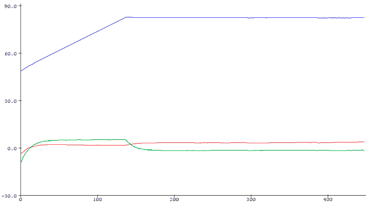
The graph above shows the evolution of the yaw, pitch, and roll variables when Arduino is powered on. The X-axis is scaled in tenths of a second. Hence, we observe that in this case, the sensor takes about 15 seconds to stabilize and provide valid measurements.
Calibrating the DMP
For the DMP measurements to be entirely accurate, it’s necessary to calibrate and adjust the offset values. For this purpose, we have this sketch that provides the offset values of our sensor. It’s necessary to execute it for each MPU6050 since there might be significant variation from one sensor to another.
// Arduino sketch that returns calibration offsets for MPU6050
//   Version 1.1  (31th January 2014)
// Done by Luis Ródenas <[email protected]>
// Based on the I2Cdev library and previous work by Jeff Rowberg <[email protected]>
// Updates (of the library) should (hopefully) always be available at https://github.com/jrowberg/i2cdevlib

// These offsets were meant to calibrate MPU6050's internal DMP, but can be also useful for reading sensors.
// The effect of temperature has not been taken into account so I can't promise that it will work if you
// calibrate indoors and then use it outdoors. Best is to calibrate and use at the same room temperature.

/* ==========  LICENSE  ==================================
 I2Cdev device library code is placed under the MIT license
 Copyright (c) 2011 Jeff Rowberg

 Permission is hereby granted, free of charge, to any person obtaining a copy
 of this software and associated documentation files (the "Software"), to deal
 in the Software without restriction, including without limitation the rights
 to use, copy, modify, merge, publish, distribute, sublicense, and/or sell
 copies of the Software, and to permit persons to whom the Software is
 furnished to do so, subject to the following conditions:

 The above copyright notice and this permission notice shall be included in
 all copies or substantial portions of the Software.

 THE SOFTWARE IS PROVIDED "AS IS", WITHOUT WARRANTY OF ANY KIND, EXPRESS OR
 IMPLIED, INCLUDING BUT NOT LIMITED TO THE WARRANTIES OF MERCHANTABILITY,
 FITNESS FOR A PARTICULAR PURPOSE AND NONINFRINGEMENT. IN NO EVENT SHALL THE
 AUTHORS OR COPYRIGHT HOLDERS BE LIABLE FOR ANY CLAIM, DAMAGES OR OTHER
 LIABILITY, WHETHER IN AN ACTION OF CONTRACT, TORT OR OTHERWISE, ARISING FROM,
 OUT OF OR IN CONNECTION WITH THE SOFTWARE OR THE USE OR OTHER DEALINGS IN
 THE SOFTWARE.
 =========================================================
 */

// I2Cdev and MPU6050 must be installed as libraries
#include "I2Cdev.h"
#include "MPU6050.h"
#include "Wire.h"

///////////////////////////////////   CONFIGURATION   /////////////////////////////
//Change this 3 variables if you want to fine tune the skecth to your needs.
int buffersize=1000;     //Amount of readings used to average, make it higher to get more precision but sketch will be slower  (default:1000)
int acel_deadzone=8;     //Acelerometer error allowed, make it lower to get more precision, but sketch may not converge  (default:8)
int giro_deadzone=1;     //Giro error allowed, make it lower to get more precision, but sketch may not converge  (default:1)

// default I2C address is 0x68
// specific I2C addresses may be passed as a parameter here
// AD0 low = 0x68 (default for InvenSense evaluation board)
// AD0 high = 0x69
//MPU6050 accelgyro;
MPU6050 accelgyro(0x68); // <-- use for AD0 high

int16_t ax, ay, az,gx, gy, gz;

int mean_ax,mean_ay,mean_az,mean_gx,mean_gy,mean_gz,state=0;
int ax_offset,ay_offset,az_offset,gx_offset,gy_offset,gz_offset;

///////////////////////////////////   SETUP   ////////////////////////////////////
void setup() {
  // join I2C bus (I2Cdev library doesn't do this automatically)
  Wire.begin();
  // COMMENT NEXT LINE IF YOU ARE USING ARDUINO DUE
  TWBR = 24; // 400kHz I2C clock (200kHz if CPU is 8MHz). Leonardo measured 250kHz.

  // initialize serial communication
  Serial.begin(115200);

  // initialize device
  accelgyro.initialize();

  // wait for ready
  while (Serial.available() && Serial.read()); // empty buffer
  while (!Serial.available()){
    Serial.println(F("Send any character to start sketch.\n"));
    delay(1500);
  }
  while (Serial.available() && Serial.read()); // empty buffer again

  // start message
  Serial.println("\nMPU6050 Calibration Sketch");
  delay(2000);
  Serial.println("\nYour MPU6050 should be placed in horizontal position, with package letters facing up. \nDon't touch it until you see a finish message.\n");
  delay(3000);
  // verify connection
  Serial.println(accelgyro.testConnection() ? "MPU6050 connection successful" : "MPU6050 connection failed");
  delay(1000);
  // reset offsets
  accelgyro.setXAccelOffset(0);
  accelgyro.setYAccelOffset(0);
  accelgyro.setZAccelOffset(0);
  accelgyro.setXGyroOffset(0);
  accelgyro.setYGyroOffset(0);
  accelgyro.setZGyroOffset(0);
}

///////////////////////////////////   LOOP   ////////////////////////////////////
void loop() {
  if (state==0){
    Serial.println("\nReading sensors for first time...");
    meansensors();
    state++;
    delay(1000);
  }

  if (state==1) {
    Serial.println("\nCalculating offsets...");
    calibration();
    state++;
    delay(1000);
  }

  if (state==2) {
    meansensors();
    Serial.println("\nFINISHED!");
    Serial.print("\nSensor readings with offsets:\t");
    Serial.print(mean_ax);
    Serial.print("\t");
    Serial.print(mean_ay);
    Serial.print("\t");
    Serial.print(mean_az);
    Serial.print("\t");
    Serial.print(mean_gx);
    Serial.print("\t");
    Serial.print(mean_gy);
    Serial.print("\t");
    Serial.println(mean_gz);
    Serial.print("Your offsets:\t");
    Serial.print(ax_offset);
    Serial.print("\t");
    Serial.print(ay_offset);
    Serial.print("\t");
    Serial.print(az_offset);
    Serial.print("\t");
    Serial.print(gx_offset);
    Serial.print("\t");
    Serial.print(gy_offset);
    Serial.print("\t");
    Serial.println(gz_offset);
    Serial.println("\nData is printed as: acelX acelY acelZ giroX giroY giroZ");
    Serial.println("Check that your sensor readings are close to 0 0 16384 0 0 0");
    Serial.println("If calibration was succesful write down your offsets so you can set them in your projects using something similar to mpu.setXAccelOffset(youroffset)");
    while (1);
  }
}

///////////////////////////////////   FUNCTIONS   ////////////////////////////////////
void meansensors(){
  long i=0,buff_ax=0,buff_ay=0,buff_az=0,buff_gx=0,buff_gy=0,buff_gz=0;

  while (i<(buffersize+101)){
    // read raw accel/gyro measurements from device
    accelgyro.getMotion6(&ax, &ay, &az, &gx, &gy, &gz);

    if (i>100 && i<=(buffersize+100)){ //First 100 measures are discarded
      buff_ax=buff_ax+ax;
      buff_ay=buff_ay+ay;
      buff_az=buff_az+az;
      buff_gx=buff_gx+gx;
      buff_gy=buff_gy+gy;
      buff_gz=buff_gz+gz;
    }
    if (i==(buffersize+100)){
      mean_ax=buff_ax/buffersize;
      mean_ay=buff_ay/buffersize;
      mean_az=buff_az/buffersize;
      mean_gx=buff_gx/buffersize;
      mean_gy=buff_gy/buffersize;
      mean_gz=buff_gz/buffersize;
    }
    i++;
    delay(2); //Needed so we don't get repeated measures
  }
}

void calibration(){
  ax_offset=-mean_ax/8;
  ay_offset=-mean_ay/8;
  az_offset=(16384-mean_az)/8;

  gx_offset=-mean_gx/4;
  gy_offset=-mean_gy/4;
  gz_offset=-mean_gz/4;
  while (1){
    int ready=0;
    accelgyro.setXAccelOffset(ax_offset);
    accelgyro.setYAccelOffset(ay_offset);
    accelgyro.setZAccelOffset(az_offset);

    accelgyro.setXGyroOffset(gx_offset);
    accelgyro.setYGyroOffset(gy_offset);
    accelgyro.setZGyroOffset(gz_offset);

    meansensors();
    Serial.println("...");

    if (abs(mean_ax)<=acel_deadzone) ready++;
    else ax_offset=ax_offset-mean_ax/acel_deadzone;

    if (abs(mean_ay)<=acel_deadzone) ready++;
    else ay_offset=ay_offset-mean_ay/acel_deadzone;

    if (abs(16384-mean_az)<=acel_deadzone) ready++;
    else az_offset=az_offset+(16384-mean_az)/acel_deadzone;

    if (abs(mean_gx)<=giro_deadzone) ready++;
    else gx_offset=gx_offset-mean_gx/(giro_deadzone+1);

    if (abs(mean_gy)<=giro_deadzone) ready++;
    else gy_offset=gy_offset-mean_gy/(giro_deadzone+1);

    if (abs(mean_gz)<=giro_deadzone) ready++;
    else gz_offset=gz_offset-mean_gz/(giro_deadzone+1);

    if (ready==6) break;
  }
}
Example with RTIMULIB-Arduino
Another option for reading the sensor is to use the RTIMULIB-Arduino library, which allows creating an Attitude Heading Reference System (AHRS) and works with a wide variety of sensors. We saw how to use this library in this post.
Download the code
All the code from this post is available for download on Github. 
