What is an analog joystick?
An analog joystick is a simple controller that we can add to our electronics and Arduino projects, which has the advantage of providing more information than we could simply obtain with buttons.
These joysticks are similar to the analog sticks found on many video game controllers or computer peripherals, such as the PlayStation 2 controller, or Xbox, which are used when a smoother and more precise control is needed than is possible with digital controllers.
If you want to learn how to use Arduino with the PlayStation 2 controller, you can check out this post
Internally, the joysticks are made up of a rocker system with two orthogonal axes coupled to two potentiometers. These potentiometers measure the position of the lever on both axes.
On the other hand, one of the axes is supported by a microswitch, which allows for the detection of the lever being pressed.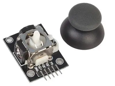
Therefore, the joysticks provide an analog signal for the position of each axis, plus a digital signal for the detection of the lever press. By having input on the X and Y axes in analog form, we can program much richer and more precise controls than we could achieve with a digital on/off control.
For example, we can increase the speed of movement of a robotic arm the higher the measurement value, or make a vehicle turn more or less quickly. If we were to do this simply with buttons, it would be impossible to achieve smooth movements, and the robot would move in a “jerky” manner.
These types of joysticks are simple and convenient devices to use, and they allow us to add control to our projects. For example, we can use them to control a servo, a robotic arm, a turret with a laser, or even complete vehicles and robots.
Price
These types of analog joysticks are inexpensive devices. We can find them for €0.75 from international sellers on Ebay and Aliexpress.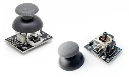
Assembly diagram
The assembly of these types of devices is simple. First, we power the module by connecting Vcc and GND, respectively, to 5V and GND of Arduino.
For the analog measurement on both axes, we connect the VRx and VRy outputs to two analog inputs of Arduino.
Finally, if we also want the digital signal from the button, we connect the SW output to a digital input of Arduino. We will use the internal Pull-Up resistors of Arduino, so no additional resistors are necessary.
The assembly diagram of the joystick would be as follows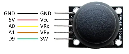
While the assembly, seen from Arduino, would be as follows.
Code examples
The code to operate the joystick is equally simple. On one hand, we read the position of both potentiometers through the analog inputs.
Regarding the button, we use a digital input to read its state.
Finally, we display the reading through the serial port. In a real example, in this part we would execute the appropriate actions, such as moving a servo, or a robot.
/*
GND - GND
Vcc - 5v
VRx - A0
VRy - A1
SW -  D9
*/

const int pinLED = 13;
const int pinJoyX = A0;
const int pinJoyY = A1;
const int pinJoyButton = 9;

void setup() {
  pinMode(pinJoyButton , INPUT_PULLUP);  //activate pull-up resistor
  Serial.begin(9600);
}

void loop() {
  int Xvalue = 0;
  int Yvalue = 0;
  bool buttonValue = false;

  //read values
  Xvalue = analogRead(pinJoyX);
  delay(100);            //a small pause between analog readings is necessary
  Yvalue = analogRead(pinJoyY);
  buttonValue = digitalRead(pinJoyButton);

  //display values via serial
  Serial.print("X:" );
  Serial.print(Xvalue);
  Serial.print(" | Y: ");
  Serial.print(Yvalue);
  Serial.print(" | Button: ");
  Serial.println(buttonValue);
  delay(1000);
}
Download the code
All the code from this post is available for download on Github. 
