
What is a matrix keyboard?
A matrix keyboard is a device that groups several push buttons and allows them to be controlled using a number of conductors less than what we would need when using them individually. We can use these keyboards as a controller for an automaton or a processor like Arduino.
These devices group the push buttons into rows and columns forming a matrix, a layout that gives them their name. A pure rectangular arrangement of NxM columns is common, although other arrangements are equally possible.
Matrix keyboards are common in electronics and computing. In fact, normal computer keyboards are matrix keyboards, being a good example of a matrix keyboard with a non-rectangular arrangement.
One of the disadvantages of using a matrix keyboard is that it can cause problems when more than one key is pressed simultaneously. This is one of the reasons why computer keyboards use a non-rectangular arrangement, grouping certain keys in different circuits (Ctrl, Alt, Shift…).
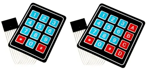
In the field of home electronics and Arduino, multiple models of matrix keyboards are sold in different formats (rigid or flexible) and with different number of keys, with configurations of 3x3, 3x4, and 4x4 being common.
We can use matrix keyboards in our electronic and robotics projects, for example, to change the operating mode of an assembly, to request a password, as directional keys to control a robotic arm or a vehicle, or to provide instructions to a robot.
Price
Matrix keyboards are cheap devices. We can find matrix keyboards with 3x4 and 4x4 buttons for €0.45 from international sellers on AliExpress or eBay.
How does a matrix keyboard work?
As we said, a matrix keyboard groups the push buttons into rows and columns forming a matrix, which allows the use of a smaller number of conductors to determine the key presses.
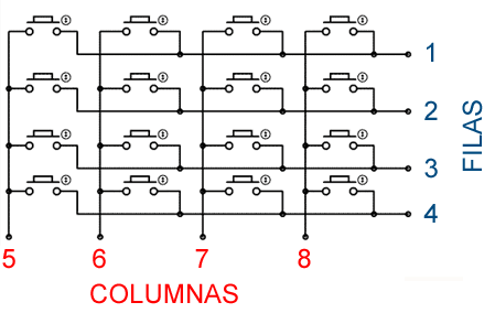
The following image shows, as an example, a rectangular arrangement of 4x4, although the operation is analogous in other arrangements. When detecting the press in column X and row Y, we will know that key (X,Y) has been pressed.
Internally, the arrangement of the push buttons is very similar to the arrangement we saw when dealing with LED matrix displays.
To detect the pressing of a key, we will act in a similar way to the simple reading of a push button. In summary, we ground one end of the push button, and connect the other end to a digital input with a pull-up resistor.
To read all the keys, we will have to scan through the rows. First, we set all the rows to 5V, and define all the columns as inputs with pull-up resistors.
Progressively, we set a row to 0V, and read the column inputs. Once the reading is done, we set it back to 5V, move to the next row, and repeat the process until all the rows have been scanned.
The role of rows and columns in the explanation is interchangeable, being able to scan through the columns and read the rows.
To detect NxM buttons, we only need N+M conductors. Therefore, the conductor saving is greater the larger N and M are, and the more similar they are to each other. (eg: 16 buttons in 2x8 need 10 conductors, and in 4x4 only 8 conductors.)
As a result, 1xM, Nx1, and 2x2 keyboards do not save any conductors, although they may be useful only for grouping the desired arrangement in the same device.
As we have mentioned, the biggest disadvantage of the matrix layout is that it can cause problems when detecting the pressing of multiple keys simultaneously.
Connection diagram
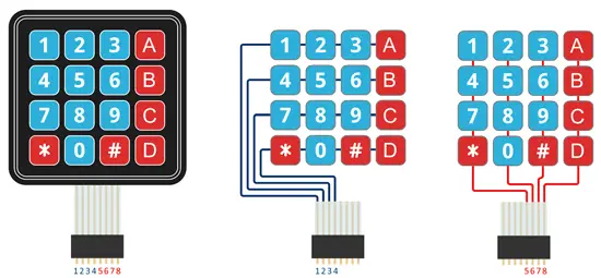
The connection diagram is simple. We simply connect all the pins to digital inputs on Arduino. For example, in the example of a 4x4 keyboard, the diagram would look like this.
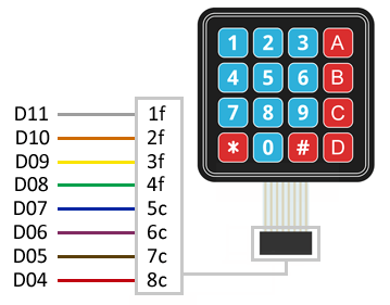
Which, seen from Arduino, would look like this.
Code examples
Without library
In the first example, we will perform the reading without using any library. To do this, we create a loop by sequentially setting the different rows to LOW, and reading by columns. If we detect the pressing of a key, the value is displayed on the serial port.
const unsigned long period = 50;
unsigned long prevMillis = 0;

byte iRow = 0, iCol = 0;
const byte countRows = 4;
const byte countColumns = 4;

const byte rowsPins[countRows] = { 11, 10, 9, 8 };
const byte columnsPins[countColumns] = { 7, 6, 5, 4 };

char keys[countRows][countColumns] = {
  { '1','2','3', 'A' },
  { '4','5','6', 'B' },
  { '7','8','9', 'C' },
  { '#','0','*', 'D' }
};

// Read the keyboard state
bool readKeypad()
{
  bool rst = false;

  // Column scanning
  for (byte c = 0; c < countColumns; c++)
  {
    // Set column to LOW
    pinMode(columnsPins[c],OUTPUT);
    digitalWrite(columnsPins[c], LOW);

    // Scan all rows checking for presses
    for (byte r = 0; r < countRows; r++)
    {
      if (digitalRead(columnsPins[r]) == LOW)
      {
        // Press detected, save row and column
        iRow = r;
        iCol = c;
        rst = true;
      }
    }
    // Return the column to high impedance
    digitalWrite(columnsPins[c], HIGH);
    pinMode(columnsPins[c], INPUT);
  }
  return rst;
}

// Initialization
void setup()
{
  Serial.begin(9600);

  // Columns in high impedance
  for (byte c = 0; c < countColumns; c++)
  {
    pinMode(columnsPins[c], INPUT);
    digitalWrite(columnsPins[c], HIGH);
  }

  // Rows in pullup
  for (byte r = 0; r < countRows; r++)
  {
    pinMode(rowsPins[r], INPUT_PULLUP);
  }
}

void loop()
{
  if (millis() - prevMillis > period)   // Non-blocking wait
  {
    prevMillis = millis();
    if (readKeypad())   // Pressed key detection
    {
      Serial.println(keys[iRow][iCol]);   // Display key
    }
  }
}
With library
There are several libraries designed to facilitate the reading of matrix keyboards in Arduino. For example, the Keypad library, available at this link. The library provides code examples, which it is advisable to review.
The following examples are a modification based on those available in the library.
#include <Keypad.h>

const byte rowsCount = 4;
const byte columsCount = 4;

char keys[rowsCount][columsCount] = {
   { '1','2','3', 'A' },
   { '4','5','6', 'B' },
   { '7','8','9', 'C' },
   { '#','0','*', 'D' }
};

const byte rowPins[rowsCount] = { 11, 10, 9, 8 };
const byte columnPins[columsCount] = { 7, 6, 5, 4 };

Keypad keypad = Keypad(makeKeymap(keys), rowPins, columnPins, rowsCount, columsCount);

void setup() {
   Serial.begin(9600);
}

void loop() {
   char key = keypad.getKey();

   if (key) {
      Serial.println(key);
   }
}
Download the code
All the code from this post is available for download on Github. 
