What is a LED matrix?
A LED matrix is a display made up of multiple LEDs in a rectangular distribution. There are different sizes, with the most common being the 8x8 LED squares.
We can combine several modules to form a much larger display. In these displays, we can show texts, drawings, or animations, such as scrolling text.
Turning on a LED matrix directly with Arduino requires using a large number of pins, which would be a waste of resources. For this reason, it is normal to always use a controller specifically designed for this function.
A commonly used controller because it is cheap and simple is the MAX7219 integrated circuit.
Price
Monochrome LED matrices (red or green) are cheap components. They are sold both with the MAX7219 controller and both components separately. It is normal that we want to buy them together.
We can find a set of 8x8 LED Matrix + MAX7129 controller for €1.27 from international sellers on Ebay or Aliexpress.
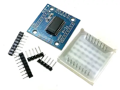
In addition, these modules incorporate input and output pins, so it is easy to connect multiple modules to form a larger display, simply by using connection jumpers.
How does a LED matrix work?
A LED matrix is made up of different LEDs, wired together in rows and columns. We can turn on a specific LED of the matrix by correctly applying HIGH and LOW values to its respective row and column.
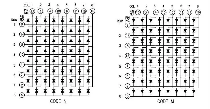
There are two possible configurations, common anode in rows or columns. Although this does not affect the explanation, you must take this into account in your setups.
If we apply HIGH and LOW values to several rows and columns simultaneously, all the LEDs at the intersections will light up. In this way, it is almost impossible to generate complex graphics.
In order to create graphics, the procedure consists of scanning through rows (or columns). We turn on all the LEDs of a single row (or column), and then move on to the next. Only one row (or column) is lit at any given moment, but by doing it quickly, the effect on our vision is to see the entire image formed simultaneously.
This effect is called “Persistence of Vision” (POV), and is a consequence of how humans perceive movement. It is widely used in electronics and computing.
Turning on an 8x8 LED matrix would require 16 digital signals and constant work from the processor to refresh the image. That is a huge amount of resources for any automaton, which we would be underutilizing to simply turn on a display.
For this reason, we use a controller like the MAX7219 that is specially designed to turn on 7-segment displays and LED matrices, and frees our processor to do much more valuable tasks.
Communication with the MAX7219 is done through SPI, so only 3 Arduino pins are required (SS, MOSI, and SCK). Furthermore, we do not entirely “occupy” these pins, since with the same bus we can control multiple devices.
Finally, the MAX7219 boards themselves generally incorporate an input and output port, so we can combine multiple controllers without any difficulty.
Assembly diagram
The electrical diagram is simple. We power the module through Vcc and Gnd, and connect the corresponding pins for SPI communication.
If we use more than one module, we would connect the outputs of each module to the inputs of the next one, and connect the first one to Arduino.
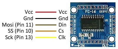
The connection seen from the Arduino side would look like this.
The Pin numbers depend on the specific model of Arduino. In Arduino Uno and Nano, they correspond to pins 10, 11, and 13. Refer to the pinout diagram for other models.
Code examples
There are several libraries to communicate Arduino with a MAX7219 controller. For example, we have the Max72xxPanel library, which requires the use of the Adafruit-GFX library.
The following example code uses these two libraries to display scrolling text across 9 connected LED matrices. Modify the code to suit your configuration and needs.
#include <SPI.h>
#include <Adafruit_GFX.h>
#include <Max72xxPanel.h>

//Vcc - Vcc
//Gnd - Gnd
//Din - Mosi (Pin 11)
//Cs  - SS (Pin 10)
//Clk - Sck (Pin 13)

const int pinCS = 10;
const int numberOfHorizontalDisplays = 9;
const int numberOfVerticalDisplays = 1;

Max72xxPanel matrix = Max72xxPanel(pinCS, numberOfHorizontalDisplays, numberOfVerticalDisplays);

String tape = "www.luisllamas.es";  //text

const int wait = 100; // In milliseconds

const int spacer = 1;
const int width = 5 + spacer; // The font width is 5 pixels

void setup() {
   matrix.setIntensity(7); // Use a value between 0 and 15 for brightness

   // Adjust to your own needs
   matrix.setPosition(0, 0, 0); // The first display is at <0, 0>
   matrix.setPosition(1, 1, 0); // The second display is at <1, 0>
   matrix.setPosition(2, 2, 0); // The third display is at <2, 0>
   matrix.setPosition(3, 3, 0); // And the last display is at <3, 0>
   matrix.setPosition(4, 4, 0); // And the last display is at <3, 0>
   matrix.setPosition(5, 5, 0); // And the last display is at <3, 0>
   matrix.setPosition(6, 6, 0); // And the last display is at <3, 0>
   matrix.setPosition(7, 7, 0); // And the last display is at <3, 0>
   matrix.setPosition(8, 8, 0); // And the last display is at <3, 0>
   matrix.setPosition(9, 9, 0); // And the last display is at <3, 0>

   matrix.setRotation(0, 1);    // Display is position upside down
   matrix.setRotation(1, 1);    // Display is position upside down
   matrix.setRotation(2, 1);    // Display is position upside down
   matrix.setRotation(3, 1);    // Display is position upside down
   matrix.setRotation(4, 1);    // Display is position upside down
   matrix.setRotation(5, 1);    // Display is position upside down
   matrix.setRotation(6, 1);    // Display is position upside down
   matrix.setRotation(7, 1);    // Display is position upside down
   matrix.setRotation(8, 1);    // Display is position upside down
   matrix.setRotation(9, 1);    // Display is position upside down
}

void loop() {
   for (int i = 0; i < width * tape.length() + matrix.width() - 1 - spacer; i++) {

      matrix.fillScreen(LOW);

      int letter = i / width;
      int x = (matrix.width() - 1) - i % width;
      int y = (matrix.height() - 8) / 2; // center the text vertically

      while (x + width - spacer >= 0 && letter >= 0) {
         if (letter < tape.length()) {
            matrix.drawChar(x, y, tape[letter], HIGH, LOW, 1);
         }

         letter--;
         x -= width;
      }
      matrix.write(); // Send bitmap to display

      delay(wait);
   }
}
Download the code
All the code from this post is available for download on Github. 
