What is a level shifter?
A level shifter is a component that allows converting logical signals of different voltage levels. It is a very useful device in a processor like Arduino.
As we know, processors operate at different voltages, with the most common being 5V, 3.3V, and, to a lesser extent, 2.8 and 1.8V. Traditionally, the most common Arduino models operate at 5V. However, most modern processors (Arduino Due, STM32, ESP8266, ESP32, Raspberry Pi) operate at 3.3V.
On the other hand, the rest of the electronic devices we normally use (sensors, controllers, displays) also operate at different nominal voltages, mainly 5V and 3.3V.
In order to connect digital devices with different nominal voltages, it is necessary to adapt the voltage levels. Otherwise, our setup is most likely not going to work, and we may even damage a device.
There are many ways to adapt voltage levels. From simple solutions, such as using a voltage divider, to specific integrated circuits that allow high-speed switching in both directions.
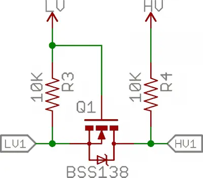
One of the most common methods is to use a simple transistor, which is a simple, high-speed, and bidirectional solution.
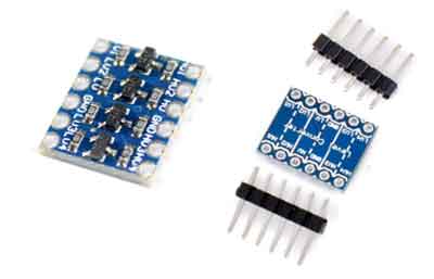
However, there are also commercial modules and integrated circuits for level adaptation. It is usually simpler and cheaper to use a commercial level shifter than to build our own from electronic components.
These level adaptation modules integrate different numbers of bidirectional channels, usually two, four, or eight.
The switching speed of these modules is fast enough to be used in voltage adaptation of communication signals, such as serial port (UART), I2C, or SPI, as long as we have enough channels for all communication lines.
Price
A level shifter module is a very cheap device. We can find a 4-channel bidirectional level shifter module for €0.25 on international sellers on Ebay and Aliexpress.
Assembly diagram
The connection of a level shifter is simple. Generally, we have two different sides, one for the higher voltage device (identified with HIGH) and one for the lower voltage device (identified with LOW).
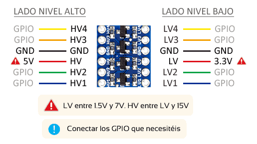
On one side, we must connect the GND of both devices to the GND of the board on the respective sides of the end adapter. GND must be common for both devices, so the GND on both sides of the board is usually internally connected.
In case of doubt, measure continuity with a multimeter on both sides of the level shifter.
On the other hand, we must provide the two reference voltages of both devices to the level shifter. For this, we have the HV pin, for the Vcc voltage of the higher voltage device, and LV for the Vcc of the lower voltage device.
- For example, if we have a 5V Arduino board and a 3.3V sensor, we can use the 3.3V output of Arduino to power the low voltage side of the level shifter.
- Another example, if we have a board with a 3.3V processor that we power at 5V because the board has an internal regulator, we can connect it to a 5V sensor by using the 5V power output.
Finally, we use as many GPIO pins (channels) as we need. The channels are bidirectional and work for both digital and analog signals, or communication systems (UART, I2C, SPI).
The behavior in one direction or the other is determined by the state of the pins in both devices (defined as input, output, high impedance, etc), as it also happens when they are connected by a cable.
Download the code
All the code from this post is available for download on Github. 
