What is a linear actuator?
A linear actuator is a device that generates rectilinear movement. We can control this type of actuators from a processor such as Arduino.
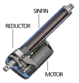
Internally, a linear actuator is formed by an electric motor with a reduction mechanism consisting of several gears and a worm screw. The screw pushes a piston or rod, which can extend or retract depending on the direction of rotation of the motor.
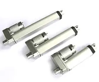
Linear actuators have the advantage of exerting great forces and large displacements. Depending on the models, they can exert forces from 20 to 150kgf, with displacements from 100 to 800mm.
As a disadvantage, linear actuators have slow displacement speeds, typically in the range of 4-20 mm/s, so the total extension time can be several minutes in the longest and slowest models.
There are linear actuators with different supply voltages, with 12V and 24V models being common. The current consumption is generally high, in the range of 3A to 5A in 12V models, and 2A-3A in 24V models.
As for control, we find three types of actuators.
- Linear actuators without control.
- Linear actuators with two limit switch buttons, which allow to detect when the piston has reached a terminal position.
- Linear actuators with a potentiometer, which provides an analog measurement of the position of the piston.
Linear actuators are widely used in all kinds of industrial applications, due to their great capacity to exert forces and good precision, which have allowed them to replace hydraulic equipment, which are comparatively much more expensive and complex to maintain.
In our electronic and robotic projects, we can use linear actuators when we need to lift heavy loads, for example, lifting tables, deploying an awning, or expanding a robotic arm.
Price
Linear actuators are expensive devices, typically between 20-80€. The price depends entirely on the length, maximum force, and speed.
Thus, we can find a linear actuator of 90Kgf at 100mm for 25€, 100kgf at 300mm for 50€, and 150kgf at 150mm for 60€, by looking at international sellers on eBay or AliExpress.
Assembly diagram
First, we will see the connection of the linear actuator motor, as this is common for all types of actuators. Subsequently, we will see the position control of the actuator, which depends on the model of actuator we have (it is even common for it not to have any).
Power supply of the linear actuator
All actuators will have two conductors to activate the electric motor that drives the worm screw. In order to extend and retract the piston, we need to be able to reverse the direction of rotation of the motor, that is, reverse the direction in which the current passes through the motor.
As we know, for this we can use an H-bridge. However, the DC controllers that we have seen (L298N and TB6612FNG) do not have enough power to control a linear actuator of large dimensions, and in most cases we would burn the controller.
A common alternative is to use two stages of SPDT relays (single pole double throw) in a configuration similar to an H-bridge. The disadvantage of using conventional relays is that we will lose speed control, since mechanical relays have long switching times.
If we want to have speed control, we must use solid state relays, or build our own H-bridge using BJT transistors or MOSFET transistors.
Linear actuator control
Regarding control, if there are digital buttons as end stops, we would simply connect them to any digital pins as we saw in the entry reading a button with Arduino.
If the linear actuator has a potentiometer that allows to determine the position of the piston, we would connect the output to an analog pin as we saw in the entry reading a potentiometer with Arduino.
Example of connecting a linear actuator
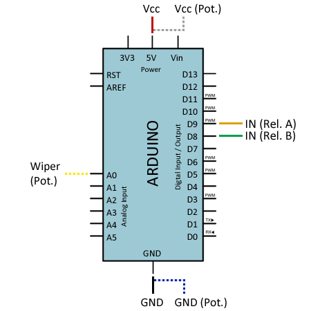
The following diagram shows the connection of a linear actuator with a potentiometer for controlling the position of the angle. If your linear actuator does not have a potentiometer, simply ignore that part and connect only the connector.
With the relays, we put each of the phases of the linear actuator to Gnd or Vcc. When the relays are off, both phases are in Gnd and the actuator is stopped. By activating one of the two relays, we put one of the phases in Vcc, keeping the other at Gnd, causing it to rotate in one direction or the other.
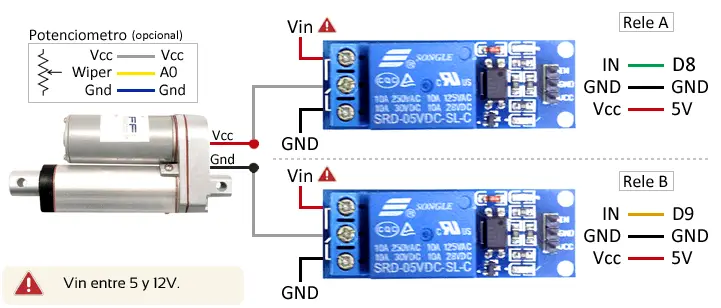
The connection, seen from Arduino, would be as follows. The connection of the potentiometer appears in dashed lines. Again, if your linear actuator does not have analog position control, ignore this part.
Code examples
Moving the actuator
In the first example, we simply move the actuator. For this, we have three functions, extendActuator(), retractActuator(), and stopActuator(), which configure the output of the relays so that the current passes through the actuator in the desired direction.
Note that before setting any relay to HIGH, there is a 250ms pause to ensure that the previous relay is set to LOW, thus preventing possible short circuits.
const int pinRelayA = 8;
const int pinRelayB = 9;

void setup()
{
  // initialize relay pins
  pinMode(pinRelayA, OUTPUT);
  pinMode(pinRelayB, OUTPUT);

  // preset relays to LOW
  digitalWrite(pinRelayA, LOW);
  digitalWrite(pinRelayB, LOW);
}

void loop()
{
  extendActuator();
  delay(5000);
  retractActuator();
  delay(5000);
  stopActuator();
  delay(5000);
}

//Set one relay one and the other off
//this will move extend the actuator
void extendActuator()
{
  digitalWrite(pinRelayB, LOW);
  delay(250);
  digitalWrite(pinRelayA, HIGH);
}

//Set one relay off and the other on
//this will move retract the actuator
void retractActuator()
{
  digitalWrite(pinRelayA, LOW);
  delay(250);
  digitalWrite(pinRelayB, HIGH);
}

//Set both relays off
//this will stop the actuator in a braking
void stopActuator()
{
  digitalWrite(pinRelayA, LOW);
  digitalWrite(pinRelayB, LOW);
}
Position control in the linear actuator
The following example shows how position control would be performed in a linear actuator with a potentiometer. The same functions as in the previous example are used to control the movement of the actuator.
The example simulates receiving a target value (Goal) through the GetGoalPosition() function. In a real program, this function would be replaced and, for example, it would receive the new setpoint via serial port, I2C, Bluetooth, or simply execute a calculation to determine the desired position.
The main control loop monitors the setpoint position. If this changes, it activates the actuator. Subsequently, it compares the setpoint value with the position and the state of the actuator to determine if it needs to stop the movement.
const int pinRelayA = 8;
const int pinRelayB = 9;
const int sensorPin = A0;

int GoalPosition = 350;
int CurrentPosition = 0;
bool IsExtending = false;
bool IsRetracting = false;

void setup()
{
  // initialize relay pins
  pinMode(pinRelayA, OUTPUT);
  pinMode(pinRelayB, OUTPUT);

  // preset relays to LOW
  digitalWrite(pinRelayA, LOW);
  digitalWrite(pinRelayB, LOW);
}

void loop()
{
  int newGoalPosition = GetGoalPosition();
  if (newGoalPosition != GetGoalPosition())
  {
    GoalPosition = newGoalPosition;
    ActivateActuator();
  }

  if (IsExtending || IsRetracting)
  {
    CurrentPosition = analogRead(sensorPin);

    if ((IsExtending = true && CurrentPosition > GoalPosition) || (IsRetracting = true && CurrentPosition < GoalPosition))
    {
      IsExtending = false;
      IsExtending = false;
      stopActuator();
    }
  }
}

int GetGoalPosition()
{
  return 300;
}

int ActivateActuator()
{
  if (CurrentPosition < GoalPosition)
  {
    IsExtending = true;
    IsRetracting = false;
    extendActuator();
  }
  if (CurrentPosition > GoalPosition)
  {
    IsExtending = false;
    IsRetracting = true;
    retractActuator();
  }
}

void extendActuator()
{
  digitalWrite(pinRelayB, LOW);
  delay(250);
  digitalWrite(pinRelayA, HIGH);
}

void retractActuator()
{
  digitalWrite(pinRelayA, LOW);
  delay(250);
  digitalWrite(pinRelayB, HIGH);
}

void stopActuator()
{
  digitalWrite(pinRelayA, LOW);
  digitalWrite(pinRelayB, LOW);
}
Download the code
All the code in this post is available for download on Github. 
