What is an IRF520N MOSFET?
The IRF520N is a very common model of MOSFET transistor that we can use to power loads at voltages and currents higher than what we can provide with the outputs of Arduino.
In the previous entry on MOSFET transistors in Arduino we saw in depth its characteristics and operation, and that we could use the cut-off and saturation mode to form a current-controlled switch with which to control large loads.
But, as we saw, not all MOSFETs are suitable for direct use with an Arduino output, given their voltage and current limitations. The IRF520N is not the most suitable MOSFET transistor to use with Arduino.
The greatest advantage of the IRF520N is that there are commercial boards that significantly simplify the assembly. These boards include integrated resistors, pins to connect to Arduino, and connection terminals to connect the load.
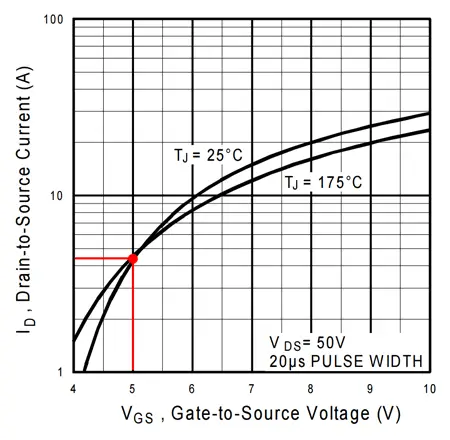
Regarding the electrical characteristics of the IRF520N, the DataSheet indicates that with a nominal Vgs of 10V it can power a load at voltages of up to 50V, providing a maximum current of 9.7A.
However, when powering the Vgs with an Arduino output at a nominal voltage of 5V, the IRF520N provides a supply voltage of 24V and a maximum current of 4A. Arduino models of 3.3V cannot use an IRF520N without pre-amplification.
For currents greater than 1A, it is necessary to add a heat sink.
Regarding the application in PWM signals, we can use the IRF520N in the analog outputs of Arduino, as long as we take into account that the switching involves an increase in the power dissipated in the MOSFET, which will require us to control its temperature and power smaller loads if it is excessive.
Despite these limitations regarding its nominal values, this type of boards provide a simple way to power a load of up to 24V and 1A. They are very convenient for use in small electronics projects or quick assemblies. Ultimately, in a definitive assembly, we would replace these components with our own stages.
For more information on higher power stages in Arduino, you can consult the entry BJT Transistors in Arduino and MOSFET Transistors in Arduino
Price
We can find a commercial board with an IRF520N to connect to Arduino for €0.60, from international sellers on eBay and AliExpress.
Taking into account that an IRF520N MOSFET transistor costs around €0.25-0.30 per unit, not including the board, resistors, and connection terminals, in general, the commercial board is more economical, without taking into account the time it would take us to assemble it.
As we have indicated, in a definitive or repetitive assembly we would consider making our own circuit. But as a quick component for testing, these commercial boards are very useful and cheap.
Assembly diagram
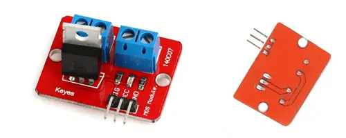
Incorporating this type of boards with IRF520N in our projects is not difficult, we only need to be clear about each part of the component and its function.
Thus, we find two different parts.
- A primary phase of low power that receives the signal from Arduino and controls the state of the MOSFET.
- A secondary phase of high power that connects the load and the external power source.
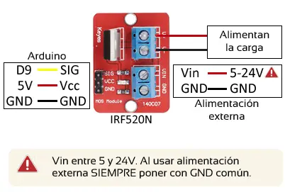
In the primary phase, we simply connect the Vcc and GND power supply of the board to the 5V and GND pins of Arduino, respectively. Finally, we connect the signal pin to a digital or analog output of Arduino.
In the secondary phase, we connect the load to the indicated connection terminal. In the other terminal, we connect the external power source that will power the load, with a maximum voltage of 24V.
When using multiple voltage sources, remember to always put all GND in common. Otherwise, you could damage a component.
The connection, seen from Arduino, would be as follows, where the D9 output has been represented, but we could have chosen any other Arduino output.
When the Arduino output is set to HIGH, the load will be connected to the external power source. Arduino only has to provide enough current to saturate the MOSFET in the state changes.
In this way, the IRF520N is behaving similarly to a switch that allows us to turn the load on or off, and whose state is controlled by the Arduino output.
Code Examples
The example codes are simple. Any of the codes we have seen when dealing with digital outputs or analog outputs will work with this assembly.
For example, the following code simply turns the load on and off at 5-second intervals.
const int pin = 9;

void setup() {
  pinMode(pin, OUTPUT);  //define pin as output
}

void loop(){
  digitalWrite(pin, HIGH);   // set the Pin to HIGH
  delay(5000);               // wait for a second
  digitalWrite(pin, LOW);    // set the Pin to LOW
  delay(5000);               // wait for a second
}
Download the Code
All the code from this post is available for download on Github. 
