In a previous post, we saw how to use a BJT transistor as an electrically controlled switch to power loads at voltage and current levels much higher than we could supply with Arduino’s digital outputs or PWM outputs.
In this post, we will see how to achieve the same behavior using a MOSFET transistor. MOSFETs have advantages over BJTs in certain aspects, but for our purposes in this post, the main advantage is that they allow us to handle large loads.
However, MOSFET transistors also have their disadvantages and peculiarities, which we will see later. This way, we will learn when it is convenient to use a BJT transistor or a MOSFET transistor, or even a combination of both.
Throughout this post, we will constantly refer to BJT transistors and their operation, which we will use as a basis for explaining MOSFET transistors. So if you are not yet familiar with their operation, it’s a good time to review the BJT transistor post.
There are also commercial boards with MOSFET IRF520N to connect directly to Arduino.
What is a MOSFET Transistor?
A MOSFET transistor is an electronic device widely used in modern electronics. For example, it is the main component of most processors, where there can be millions of transistors in each integrated circuit.
MOSFETs are a subfamily of the FET transistor family (field effect transistor). There are many other FET subfamilies, such as JFET (join field effect transistor), CMOS, and TFT.
Like BJT transistors, FET transistors are useful in multiple applications. Some of the main ones are acting as an amplifier and acting as an electrically controlled switch. In this post, we are interested in the latter function of the transistor.
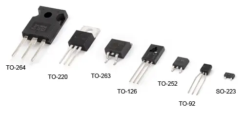
Another similarity with BJT transistors is that there are many models of FET transistors, each with its own characteristics. They also come in a wide variety of packages, so it is not possible to distinguish the characteristics of a transistor at a glance, and you must consult its Datasheet to know its characteristics.
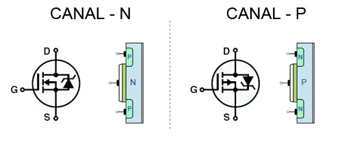
Like BJT transistors, a FET transistor has three terminals, although their names are different from those found in BJT transistors.
- Gate, similar to the base of the BJT
- Source, similar to the emitter of the BJT
- Drain, similar to the collector of the BJT
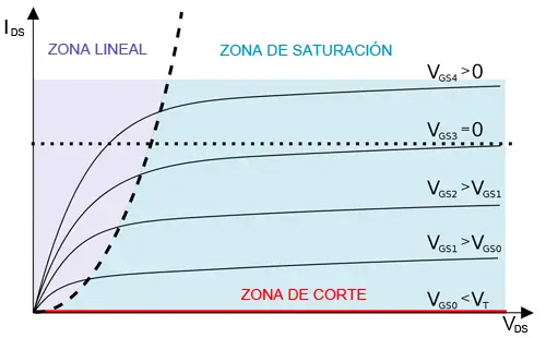
Also similar to BJT transistors, FET transistors have 3 modes of operation, although the active region of the BJT is replaced by the linear or ohmic region. (And it’s not just a simple name change; both regions actually have very different behaviors)
- Cut-off, the transistor behaves as an open circuit between Source and Drain
- Saturation, it behaves as a short circuit between Source and Drain
- Linear Region, it behaves as a variable value resistor
And similar to the case of BJT transistors, to turn on a load we are interested in making the FET work as an electrically controlled switch, for which we will use the cut-off and saturation modes, avoiding the linear region.
However, FET transistors have important differences from BJT transistors. First, their operation is not based on the junction of semiconductor materials, but on the creation of a conduction channel between Source and Drain within a single semiconductor material. The width of this channel is controlled by the Gate terminal.
Another important difference is that the state of a FET transistor is controlled by the voltage applied to the Gate, unlike BJTs whose state depended on the current flowing through the base. Therefore, FETs are voltage-controlled devices, while BJTs are current-controlled devices.
Another great advantage is that in saturation mode, MOSFET transistors behave like a very low-value resistor, while BJT transistors always imposed a voltage drop. This allows MOSFET transistors to handle huge loads with little energy dissipation.
There are more differences between both devices that, although they do not directly influence this post, are worth reviewing.
MOSFETs are much more symmetrical devices than BJTs (the behavior from Drain to Source and vice versa is similar). Furthermore, they have a high impedance from the Gate (on the order of 100MΩ), which is a great advantage when combining them to form digital circuits.
In general, switching times are faster than BJTs. They also generate less noise and are less sensitive to temperature.
Finally, MOSFET transistors are easier to manufacture, and can also simulate the behavior of a resistor. This makes them great candidates for forming integrated circuits and processors.
Determining the MOSFET State
If we recall the BJT transistor post, a BJT transistor behaves as a linear amplifier of the base current (Ib) and the collector current (Ic), with a certain hFE factor, which gives rise to a series of models and calculations.
In the case of MOSFETs, the current flowing through the drain (Id) has a quadratic relationship with the voltage between Gate and Source (Vgs). Given this quadratic relationship, instead of proposing a mathematical model, we recommend consulting the Datasheet graphs to determine the transistor’s operating point.
However, to be able to use and, above all, to correctly choose a transistor model for our setup, we must understand two aspects of FET operation.
On one hand, the MOSFET transistor behaves as a variable resistor between Drain and Source. In the linear region, the resistance value depends on the Vgs voltage. Past the saturation point, the Rds resistance decreases drastically (this Rds value in saturation is often called Rdson).
On the other hand, the transistor Gate behaves like a capacitor. That is, the transistor needs to absorb a certain amount of electrical charge (equivalently, current for a certain time) to change its operating mode.
In summary, to saturate the MOSFET we will need two things:
- Exceed a threshold in the Gate voltage (Vgs)
- Provide enough charge for the MOSFET to saturate
These two facts are fundamental to understanding the operation of a MOSFET and being able to choose the appropriate model for our setup, and when it is preferable to use a BJT transistor.
Power Dissipated in the MOSFET
Another fundamental aspect for designing circuits with MOSFETs is the power supported by the transistor itself, as it must be able to dissipate this energy without damage.
The power supported by the MOSFET is its resistance, multiplied by the square of the current flowing through it.
Quantitatively, for each of the possible operating regions:
- In the cut-off region, Rds is determined by Vgs, but Ics is zero, so the dissipated power is zero.
- In the saturation region, Ids is large, but Rdson is very small, so the dissipated power is very small.
- In the linear region, Ids can be large, and Rds is “not small”, so the dissipated power can be large.
Therefore, a MOSFET transistor only has to withstand significant power in the linear region, especially as we approach the saturation point. Once saturated, the MOSFET can withstand a large current with little energy dissipation.
Therefore, if we want to use the MOSFET as a switch, we will avoid the linear region because in this region the dissipated energy is high, which converts into heat and a temperature increase that can damage the transistor.
If the power dissipated by the MOSFET is too high, we will need to add a heatsink.
Using a MOSFET with Arduino
We come to the part of choosing a MOSFET that works correctly with Arduino, and this is where our idyllic relationship with FET transistors gets complicated.
When choosing a MOSFET, we can be dazzled by the high nominal current values (20-60A), which make them seem much better than a BJT transistor or a Darlington pair (0.5-4A).
Furthermore, although somewhat more expensive than BJTs, MOSFETs are still cheap devices. We will find all kinds of prices, as there are many models with different characteristics. But, in general, we can say that a typical price range is between €0.10 to €0.60.
However, to choose a MOSFET for Arduino we must keep in mind that Arduino outputs operate at a nominal voltage of 5V (or 3.3V, depending on the model) and provide a maximum current of 40 mA, with the recommended maximum being 20 mA.
Most MOSFETs have a nominal Vgs voltage of 10V, so at the 5V provided by the Arduino output, the maximum current that the MOSFET can provide is much lower than its nominal current. Even in some transistor models, it may not be enough to saturate the MOSFET. This situation is logically even worse in the case of 3.3V Arduino models.
Furthermore, even if we accept this Id current lower than the nominal one, we must remember that the MOSFET needs to absorb a certain amount of charge to change state. With the current limitation of Arduino outputs, transitions are slower and the time the transistor spends in the linear region is longer, which means greater energy dissipation and heating.
MOSFET Models for Arduino
There are many MOSFET models available, but not all are recommended for direct use with a processor like Arduino due to the voltage and current limitations of its outputs.
Common MOSFET models are the IRF520, IRF530, and IRF540, with a nominal Id current of, respectively, 9.2A, 14A, and 28A. However, when using these transistors with an Arduino and a Vgs of 5V, the Id values drop to 1A, 2A, and 11A.
On the other hand, the N series, IRF520n, IRF530n, and IRF540n, with a nominal Id current of 9.7A, 17A, and 33A, when connected directly to Arduino with a Vgs voltage of 5V, the Id values drop to 3A, 11A, and 12A, better than the previous ones but far from spectacular.
To solve this, there is a special type of MOSFET capacitors called logic level transistors, specifically designed to switch at the low voltages typical in TTL. In contrast, the price is somewhat higher than regular MOSFETs.
Thus, the series of logic transistors IRL520, IRL530, and IRL540 saturate without problems at 5V, providing an Id of, respectively, 9.2A, 15A, and 28A.
But they are not the only logic MOSFET transistors available. Among the many models, we find the IRLZ44 which provides an Id of 50A, or the IRLB3034PbF which provides a brutal Id of 190A.
Wiring Diagram
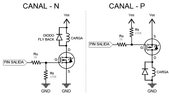
Similar to BJT transistors, which came in two subfamilies called NPN and PNP, there are two variants of FET transistors called N-Channel and P-Channel.
The operation of both variants is analogous, but determines the position in the setup.
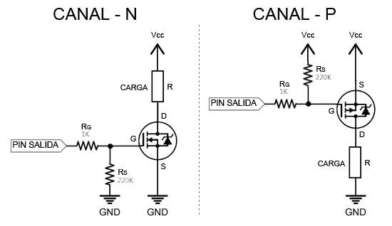
Mnemonic rule: The P-Channel transistor goes in the “Positive” part of the circuit. The N-Channel transistor goes in the “Negative” part of the circuit.
The two resistors used in the setup are necessary for the correct operation of the system and serve different functions.
On one hand, Rg, the resistor on the Gate, serves to limit the current “demanded” by the Gate. Higher values mean lower currents, and therefore lower consumption in Arduino. On the other hand, decreasing the resistor value favors faster transitions, so the transistor spends less time in the linear region and heats up less during switching. Typical values are 470 to 4k7.
On the other hand, Rs simply puts the transistor in a known state (GND) when the Pin is in an indeterminate state (high impedance), for example, during program startup, which could cause the MOSFET to turn on and off. A high resistor value, from 100K to 1M, is enough to pull the Gate to ground.
MOSFET with Inductive Loads
Exactly the same as with BJT transistors, when using a MOSFET to power inductive loads (motors, coils, electromagnets) we must add a safety device called a Flyback diode.
This diode provides a path of minimum resistance, which allows dissipating the induced currents produced by the magnetic field of the inductive load when it is disconnected from the current, and which could damage the transistor or Arduino.
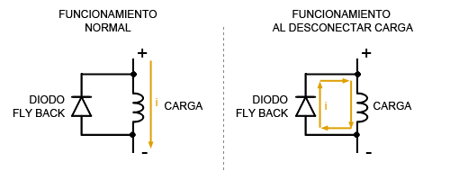
Therefore, for inductive loads and incorporating the Flyback diode, the setup would be as follows.
MOSFET with PWM Outputs
In the BJT post, we saw that they were suitable for generating an amplified PWM signal, with no more need than connecting them to an analog output of Arduino.
We might think that MOSFET transistors are even better for generating PWM outputs, given that they can power larger loads and their switching time is much faster than BJT transistors.
However, this is not the case. In general, MOSFET transistors are not suitable for generating PWM signals simply by connecting them directly to an Arduino output, not even in logic level transistor models.
This is because both the voltage and, especially, the current provided by an Arduino output is not enough to saturate the MOSFET quickly. This causes the transistor to spend excessive time in the linear region, increasing losses.
To deal with these limitations we can:
- Limit ourselves to small loads, which demand currents lower than the nominal.
- Consider replacing it with a Darlington pair.
- Implement a previous power amplification stage with a BJT (we’ll see this next).
Before using a MOSFET in a PWM, it’s a good idea to think a little before making the setup, and always keep in mind the power and temperature supported by the transistor.
Using a BJT Stage as a Driver
Throughout this post, we have seen that the voltage and current limitations imposed by Arduino outputs (and in general by any processor or PLC) force us to reduce the loads we can power with a MOSFET, or to use special logic level transistors.
This situation is even worse in the case of PWM outputs, since the current limitation forces the MOSFET to spend more time in the linear region, increasing the dissipated power and its temperature.
One way to eliminate these restrictions is to use a pre-amplification stage between the Arduino output and the MOSFET. This stage, or driver, can be a circuit formed by a simple small BJT (N2222, BC337 or similar).
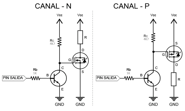
This stage receives the Arduino output and provides the MOSFET with the voltage and current it needs to fully saturate, and with fast switching speed.
With this type of circuit, we can take full advantage of the MOSFET, allowing it to provide large currents even in PWM outputs. But, on the other hand, it adds components and complexity to the setups.
Therefore, there is no single solution for choosing when a BJT, a MOSFET directly, or a MOSFET with pre-amplification is more appropriate. It is a design decision that you must make individually for each of your setups, based on everything we have seen in this post.
Download the Code
All the code from this post is available for download on Github.