What is an MPR121?
The MPR121 is a capacitive sensor controller that can be used with a processor like Arduino to control up to 12 touch pads.
Using this integrated circuit makes it much easier to use capacitive sensors as it includes filtering, debouncing, and the rest of the logic to read sensors correctly. It also has adjustable sensitivity by software configuration to adjust the sensitivity.
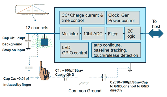
It has 12 capacitive sensor inputs. By touching one of the input pads, we vary the capacitance of the system. The MPR121 measures the capacitance, filters it, and determines the state of the pad, avoiding us having to perform these operations.
Additionally, 8 of the electrodes (pins 4 to 11) have basic GPIO functionality. On the other hand, it has a “virtual” 13th electrode, which can be used as a proximity sensor.
Communication with the MPR121 is done via I2C, so it is very easy to connect it with a processor like Arduino. The address can be configured with the Address pin among 4 possible options, for a total of 48 touch points on a single I2C bus.
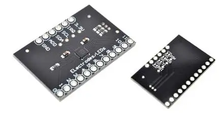
The power supply is 3.3V, although some modules add a voltage regulator and a level shifter to be able to use it with a 5V processor. Otherwise, we will have to add the level shifter ourselves.
In addition to detecting touch sensors, the MPR121 can be used in general-purpose applications for detecting changes in capacitance, such as liquid level measurements or object detection sensors.
Price
MPR121 devices are inexpensive. We can find a module with MPR121 for €1.30 from international sellers on Ebay and Aliexpress.
How does an MPR121 work?
For the measurement of capacitance, the MPR121 charges and discharges each of the electrodes sequentially, applying a small current, and measures the voltage decay. The maximum voltage applied is measured using an internal 10-bit ADC.
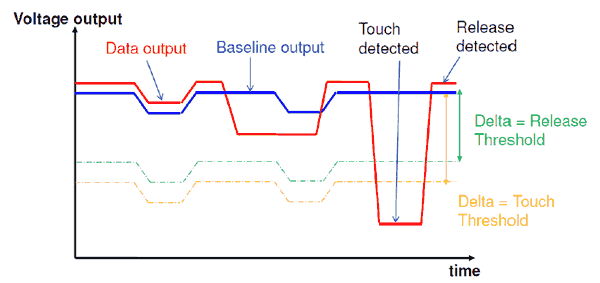
The measurement obtained goes through 3 filters with different characteristics. The first two filters eliminate the noise from the measurement. The third filter is a low-pass filter, which provides a reference measurement (baseline).
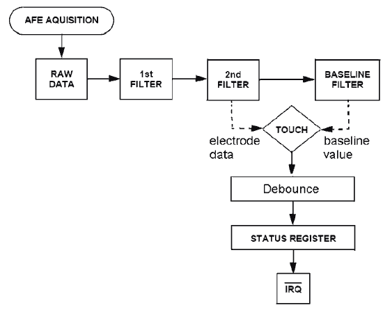
By comparing the value after the second filter with the reference provided by the third filter, the MPR121 is able to detect rapid variations in the capacitance of the electrodes. This way of operating allows the MPR121 to have a self-calibration capability, ignoring changes in electrode capacitance over time, and only detecting abrupt changes in capacitance.
On the other hand, the measurement of the “virtual” 13th input is obtained by combining the response of the 12 physical electrodes, obtaining a kind of “large capacitive sensor” that can be used for presence detection.
The MPR121 is designed to have low power consumption. The supply voltage is 1.71V to 3.6V, and the consumption is 29uA (at a sampling period of 16ms), and 3uA when not measuring.
The supply voltage is 3.3V, and most modules do not have a voltage regulator for the power supply, so powering at 5V will damage the module. However, many modules do include a level converter on the I2C communication lines, so it is safe to communicate from a 5V processor.
Assembly diagram
The connection is simple, as communication is done via I2C. Simply power the module from Arduino through the 3.3V and Gnd pins. On the other hand, connect the SDA and SCL pins to the corresponding pins of our Arduino model.
The I2C address can be configured by connecting the Address pin. By default, it has a 100K pull-down resistor to Gnd, giving the address 0x5A. It can be connected to 3.3V, SDA, or SCL to change the address to 0x5B, 0x5C, or 0x5D, respectively.
Optionally, the IRQ interrupt pin is connected to 3.3V with a pull-up resistor. When the sensor detects a change in any of the sensors, the pin goes to 0 until the data is read via I2C. We can connect this pin to an interrupt input to perform the reading when detecting changes.
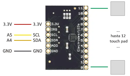
The connection, seen from Arduino, would be as follows.
If you connect the MPR121 to 5V, you will immediately and permanently damage it.
Check that your module has a level converter on the I2C lines before connecting it directly to 5V. If it does not include it, you will need to add it externally, or you may damage the module.
Code examples
To read the MPR121, we will use the library developed by Adafruit, available at this link.
The library provides code examples, which it is advisable to review. The following example is a modification based on those available in the library, which reads the 12 capacitive sensors and displays a message on the serial port when touching or releasing any of them.
#include <Wire.h>
#include "Adafruit_MPR121.h"

Adafruit_MPR121 mpr121 = Adafruit_MPR121();
uint8_t mpr121Address = 0x5A;

uint16_t lasttouched = 0;
uint16_t currtouched = 0;

void setup() {
  Serial.begin(9600);

  // Start the sensor
  if (!mpr121.begin(mpr121Address)) {
    Serial.println("MPR121 not found");
    while (1);
  }
  Serial.println("MPR121 started");
}

// Returns true if the pad has been touched
bool isPressed(uint8_t channel)
{
  return bitRead(currtouched, channel) && !bitRead(lasttouched, channel)
}

// Returns true if the pad has been released
bool isReleased(uint8_t channel)
{
  return !bitRead(currtouched, channel) && bitRead(lasttouched, channel)
}

void loop()
{
  // Get sensor data
  mpr121.updateTouchData();
  currtouched = mpr121.touched();

  // Check for changes in all channels
  for (uint8_t sensorChannel  = 0; sensorChannel < 12; i++)
  {
    if (isPressed(sensorChannel) )
    {
      Serial.print(sensorChannel );
      Serial.println(" touched");
    }

    if (isReleased(sensorChannel))
    {
      Serial.print(sensorChannel);
      Serial.println(" released");
    }
  }

  lasttouched = currtouched;
}Download the code
All the code from this post is available for download on Github.

