As our projects grow and, especially, as we interact with higher power systems—such as a 24V LED strip, a 15V motor driver, or even the 230V mains—we will need a way to isolate and protect the control layer electronics.
Otherwise, any connection error, component malfunction, signal noise, or temporary spikes (e.g., from motor startups) could fry our electronics.
Destroying a €1.60 Arduino might not be a great loss, but imagine it’s connected via USB to your laptop and you fry that too. Or imagine that, due to a current spike, the control electronics burn out, preventing a safety mechanism from activating, causing an actuator to move uncontrollably and damage everything in its path, or making a vehicle crash.
There is even a real danger to people’s safety, both from the transmission of high-power current and from the action or inaction of a system if its controlling electronics are damaged.
Industrially, the need to isolate two circuits while maintaining communication between them has existed for a long time, both for equipment safety and for the safety of people themselves.
Another common use requiring isolation is data transmission. Communication lines can accumulate spikes, noise, or interference, which must be isolated to prevent damage to the transmitting and receiving systems.
There are several ways to achieve this isolation between circuits, with one of the most common being the use of an optoisolator, devices widely used in electronics and which we will dedicate this post to today.
What is an Optoisolator?
An optoisolator is a device that uses light to connect two electrical circuits while maintaining galvanic isolation between them, meaning there is no electrical path for charge to flow between the two circuits.
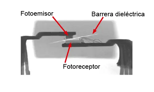
The only communication between both circuits is through light, with no electrical contact. A dielectric barrier is often incorporated between the emitter and receiver to increase isolation to the order of kV.
By having galvanic isolation, we protect the control electronics from any type of noise, overvoltage, spike, harmonic, induced current, etc., that could damage it. In case of a catastrophic failure, the optoisolator might be destroyed, but we would only have to replace it, and it’s an inexpensive component.
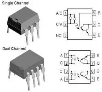
Optoisolators are usually provided in DIP and SMD integrated circuits, with 4 to 16 pins. There are different types of optoisolators, each requiring a different number of pins. Furthermore, there are ICs with one or several optoisolators inside (single, dual, and quad). The combination of these factors determines the number of pins on the IC.
There are many variations of the standard optoisolator. There are optoisolators where a single emitter activates several receivers. Some optoisolators are designed so that the output is linear to the input, allowing them to transmit signals with little distortion. Others incorporate signal amplification or offset functions. There are also bidirectional optoisolators, made up of two LEDs. In short, it’s a whole world.
As you can see, there can be a big difference from one optoisolator to another. Therefore, review the Datasheet of your component before making any assembly.
How does an Optoisolator work?
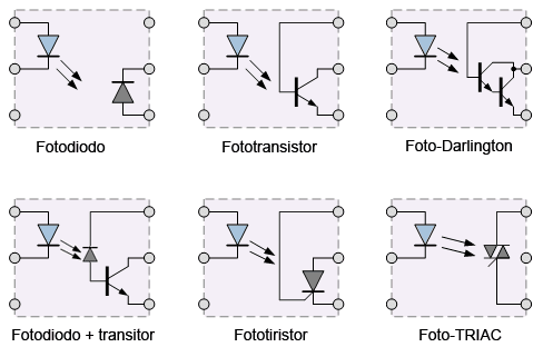
Optoisolators incorporate an emitter and a receiver in a single compact integrated circuit. In most cases, the emitter is a GaAs IR LED, while the photoreceiver can be a phototransistor, a photodiode + transistor, a phototriac, among others.
The characteristics of the optoisolator depend on the type of receiver used and the specific optoisolator model. Some of the main characteristics involved in choosing an optoisolator are:
- Rated voltages and currents for both the primary and secondary circuits.
- CTR (Current Transfer Ratio), the ratio between the energy provided by the receiver in the secondary and the energy absorbed by the emitter in the primary.
- Switching speed (bandwidth), with switching times frequently ranging from 1 to 20μs.
| Receiver | Speed | CTR |
|---|---|---|
| Photodiode | Very fast | Low |
| Phototransistor | Medium | Medium |
| Photodarlington | Medium | High |
| Photodiode + transistor | Fast | Medium |
| Photodiode + darlington | Fast | High |
| Photothyristor | Slow | High |
| Phototriac | Slow | Very High |
Optoisolators with Arduino
There are many optoisolators we can use with Arduino. In general, they are inexpensive devices. We can find them for a cost, depending on the model, from €0.05 to €0.30, by searching international sellers on eBay or AliExpress.
Some common models are the 817c series (PC817, EL817…), optoisolators with a phototransistor receiver, costing about €0.05.
The 4N2X series (4N25, 4N26) and 4N3X series (4N35, 4N38) are also common, all with phototransistor receivers and costs between €0.10 and €0.20.
Among the photodiode + transistor (high-speed) optoisolators, we have the 6N13X (6N135 and 6N137), costing about €0.30.
Finally, the MOC3063 and similar are optoisolators with a phototriac receiver, costing about €0.20.
How to use an Optoisolator with Arduino?
In this post, we will focus on optoisolators with phototransistors (normal or Darlington) and photodiode + transistor. In this type of optoisolator, the secondary behaves similarly to a switch, controlled by the primary circuit.
Arduino as an Optoisolated Signal Transmitter
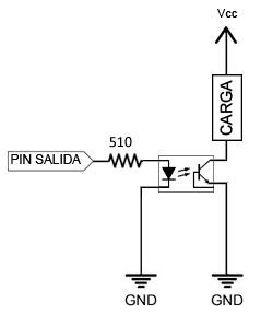
If we want to transmit an optoisolated signal, meaning Arduino is part of the primary circuit, the connection is simple. On one side, we power the primary circuit, which is just a simple LED. Therefore, we only need to put a series resistor to limit the current, as we saw in the post Encender un LED con Arduino.
The resistor value will vary depending on the nominal (forward) current of the optoisolator’s diode, its voltage drop, and the supply voltage, but a range of 220-500 Ohm is reasonable.
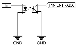
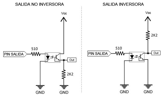
The secondary behaves like a switch. If we only want to drive a load, we simply connect one of the phases so the optoisolator controls the load.
If we want a digital output (LOW or HIGH), we will need to use a Pull-Up or Pull-Down resistor, respectively.
In some assemblies, you will see a protection diode added to the optoisolator. This diode is optional and only makes sense if there is a possibility of applying a reverse current to the primary circuit greater than the diode’s breakdown voltage.
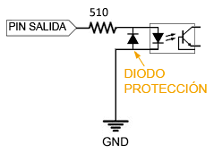
If you are powering from Arduino and, given that the breakdown voltage in many optoisolators is 6V, in general, this diode will not be necessary because the optoisolator is protected even if you accidentally reverse the wires.
Arduino as an Optoisolated Signal Receiver
If we want Arduino to receive an optoisolated signal emitted from another device, we simply have to read the secondary as if it were a pushbutton, as we saw in the post Leer un pulsador con Arduino.
If we use Arduino’s internal Pull-Up resistors, we won’t need to add any additional components.