What is a Peltier plate?
A Peltier plate is an electrothermal device that allows cold to be generated from electricity.
A Peltier plate acts as a solid-state heat pump, that is, it is capable of using energy to transfer heat from a cold focus to a hot one, opposing the temperature gradient.
 During its operation, one side of a Peltier plate heats up while the other side cools down. Since there are simpler and more efficient ways to generate heat, the usual use of these devices is for generating cold.
However, the laws of thermodynamics insist stubbornly on their obligatory compliance, so if we turn on a Peltier plate directly, the heat from the cold side and the hot side will equalize. In addition to the heat dissipation from the energy consumed by the plate, this will cause the temperature of the plate to rise rapidly.
To make a Peltier plate work, we must remove the heat generated from the hot side, for which we must install a dissipation system. At a minimum, we should place a heatsink with a fan on the hot side. A heatsink on the cold side is also recommended.
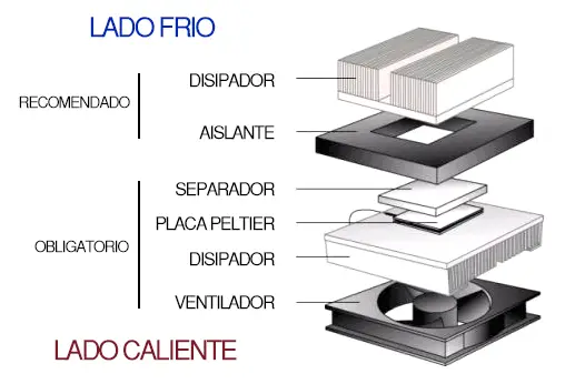
Do not operate a Peltier plate without a dissipation system. It will quickly raise its temperature and melt in a few seconds. The temperatures reached are high enough to be dangerous to the touch.
Peltier plates have the disadvantage of requiring large currents to operate. In addition, they have a relatively low efficiency as a cooling mechanism.
However, their simplicity, not requiring moving parts or fluid circuits, has made them popular as mechanisms for generating cooling in portable equipment such as small refrigerators or drink coolers.
The low temperatures reached on the cold side can lead to the condensation of water. This water can damage the elements we want to cool, especially in the case of electronic components.
Price
Until recently, Peltier plates were prohibitively expensive devices, but currently, their price has decreased significantly, and they are affordable components.
We can find Peltier plates like the TEC1 12706, for €1.55 from international sellers on eBay and AliExpress.
The TEC1 12706 has dimensions of 40x40x3mm and contains 127 pairs of junctions. The electrical power is 60W, with a nominal voltage of 12V and a nominal current of 5A.
It can reach a maximum temperature differential of 65ºC between both sides under ideal conditions. The temperature range in which it can operate without damage is -55ºC to 83ºC. The average life of a Peltier plate exceeds 200,000 hours if it is kept within the appropriate temperature range.
The cooling efficiency of the plates, without taking into account the energy cost of the fan, is around 20-25%. That is, the TEC1 12706 can remove about 12-15W of heat. However, the final value depends greatly on the ambient temperature and the dissipation system installed.
There are other models in the TEC1 series, such as the 12710 with an electrical power of 100W for about €3, or the 12715 with an electrical power of 138W for about €3.40. However, keep in mind that the current consumption of these models is very high, and we will have problems turning it on with a normal 10A relay.

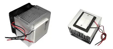
In addition, we will have to add the dissipation system. We can use a cheap CPU heatsink that we can find for about €6.
We can also recycle an old heatsink; Pentium 4 type heatsinks fit very well and are easy to find second-hand or from retired computers.
How does a Peltier plate work?
The Peltier effect is one of the three classic thermoelectric effects (SeedBeck, Peltier, and Thomson).
The Seebeck effect was discovered in 1821 by the German physicist Thomas Johann Seebeck. By establishing a closed circuit between two different metals and applying a temperature difference between both junctions, an electric current appears.
In 1832, the Frenchman Jean Charles Athanase Peltier discovered the opposite effect, that is, in a closed circuit formed by two different metals, when a current flows a temperature difference appears between both junctions.
The reason for both phenomena is the different concentration of free electrons between both metals that establish two potential barriers to the passage of electrons, inverse at each junction, which produces an emission or absorption of heat.
However, their practical applications had to wait because the effect in metals is small. It was not until 1947 with the invention of the transistor and the development of high-purity doped semiconductor materials that materials were available to take advantage of these effects.
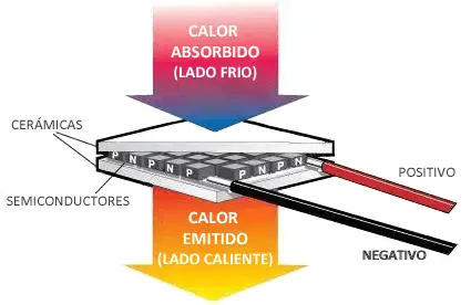
A Peltier plate is formed by multiple cells of N and P materials located between two ceramic faces. Tellurium and Bismuth are usually used as semiconductors and aluminum oxide for the ceramic plates.
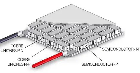
The different cells are connected in series, and the junctions are arranged so that the N-P junctions are in contact with one of the ceramic faces of the Peltier plate and the P-N junctions with the other face.
By passing current through the device, one side absorbs heat and the other emits it. The role of each face depends on the direction of the current. In fact, it is possible to reverse the heat flow by reversing the direction of the current.
Assembly diagram
Peltier plates consume a large amount of current, so the simplest way to turn them on is to use a relay output.
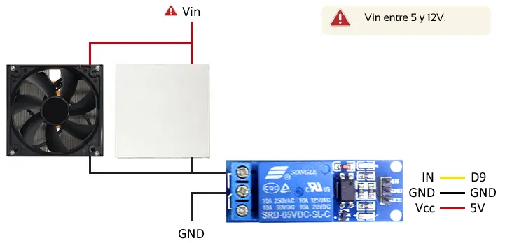
We connect the Peltier plate and the fan to 12V, interposing the relay as a switch.
On the other hand, we power the relay electronics by connecting Vcc and GND respectively to 5V and GND of Arduino. Finally, we connect the IN pin to one of the digital outputs of Arduino.
To assemble the devices, you can screw them, if the heatsinks have the holes used, or use plastic ties to form a “sandwich” with the Peltier plate in the middle.
Alternatively, we can use a suitable MOSFET, as we saw in the entry Controlling large loads with Arduino and MOSFET transistor
Assembly code example
The required code is simple since to control our Peltier plate, we only need to use a digital output, as we saw in the entry digital outputs.
For example, the following code would simply turn on the plate for 5 seconds and then turn it off for 10 seconds.
const int pin = 9;

void setup() {
  pinMode(pin, OUTPUT);  //define pin as output
}

void loop(){
  digitalWrite(pin, HIGH);   // set the pin to HIGH
  delay(5000);               // wait 5 seconds
  digitalWrite(pin, LOW);    // set the pin to LOW
  delay(10000);              // wait 10 seconds
}
Logically, this is not very interesting. However, we can combine it with one of the many temperature sensors we have seen (thermistor, LM35, DS18B20, DHT11/DHT22) to turn on the plate according to the sensor measurement, keeping the temperature constant.
Let’s assume that we have a certain function GetTemperature() that provides us with the sensor measurement. We must replace this function with the appropriate calculation, depending on the sensor we are using.
Now we define a certain hysteresis through two thresholds. When the temperature exceeds the upper threshold, it will trigger the Peltier plate to turn on. It will remain on until it reaches a lower threshold and will finally turn off when it reaches it.
If we defined a single threshold for activation and deactivation, we would have multiple on and off cycles, and the sensor would be very sensitive to noise. In the end, we would end up damaging the relay.
const int pin = 9;

const float thresholdLOW = 20.0;
const float thresholdHIGH= 30.0;

bool state = 0; //Peltier plate off or on

float GetTemperature()
{
  return 20.0;  //replace as per the sensor used
}

void setup() {
  pinMode(pin, OUTPUT);  //define pin as output
}

void loop(){
  float currentTemperature = GetTemperature();

  if(state == 0 && currentTemperature > thresholdHIGH)
  {
      state = 1;
      digitalWrite(pin, HIGH);   // turn on the Peltier plate
  }
  if(state == 1 && currentTemperature < thresholdLOW)
  {
      state == 0;
      digitalWrite(pin, LOW);   // turn off the Peltier plate
  }

   delay(5000);  // wait 5 seconds between measurements
 }
Download the code
All the code from this post is available for download on Github. 
