What is a relay?
A relay is an electromechanical device that allows a processor like Arduino to control loads at a voltage or intensity level much higher than what its electronics can support.
For example, with a relay output, we can turn on or off AC loads at 220V and intensities of 10A, which covers most of the domestic devices that we connect at home to the electrical grid.
Relay outputs are very common in the field of process automation, and almost all programmable logic controllers include relay outputs to operate loads such as motors, pumps, air conditioners, lighting, or any other type of installation or machinery.
Physically, a relay behaves like a “conventional” switch but, instead of being activated manually, it is activated electronically. Relays are suitable for operating both AC and DC loads.
A relay has two circuits:
- The primary circuit is connected to the low-voltage electronics, in our case Arduino, and receives the on/off signal.
- The secondary circuit is the switch responsible for turning the load on or off.
As they are electromechanical devices that require the movement of internal components for their operation, the switching time of a relay is high, on the order of 10ms.
As a result, relays cannot be used with a PWM signal, or any other type of medium-high frequency signal. In case of having this need, you should use another device, such as a BJT transistor, a MOSFET, or solid-state relays, depending on the characteristics of your project.
The device’s lifespan is determined by the number of switches. However, it is typically on the order of 100,000 to 1,000,000 switches, so in normal use, they are durable and reliable components.
There are many relay models, with different electrical characteristics for both the primary and secondary circuits. We must choose a relay that suits the needs of our design, that is, that the primary has a voltage range compatible with our electronics and the secondary can support the voltage and current required by the load.
Relays are fundamental components in our electronic, home automation, and Internet of Things projects. We can use relay outputs to interact and control almost any device we have at home.
For example, we can turn on a fluorescent tube from our mobile phone, turn the boiler on or off by acting on the thermostat, deploy an awning or lower a blind, turn on an irrigation system, activate or turn off external hard drives, among countless applications.
Price
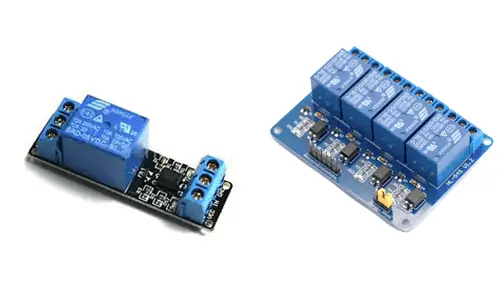
Relays are inexpensive devices. There are integrated boards ready to connect to Arduino, with different sizes and number of channels. Each channel is a switch completely independent of the others, allowing you to control multiple loads with a single processor.
You can find a one-channel relay for €0.55, a two-channel relay for €1.10, a four-channel relay for €2.20, and an eight-channel relay for €4.10, from international sellers on eBay and AliExpress.
These commercial boards mount relays with a limitation of 250V in alternating current (AC) or 30V in direct current (DC). The maximum current they can support is 10A. This is equivalent to a load of 2,300W at 230V AC, and 300W at 30V DC.
Whenever possible, we will choose assemblies with an optocoupler. The optocoupler is a device that electrically isolates the primary and secondary circuits, providing additional protection for Arduino against catastrophic failure on the relay board.
Since it is a simple device, we can also assemble it ourselves. In general, it is not worthwhile because only the relay would cost us more, not to mention the time required and the quality that we could obtain, so it is normal for us to use a commercial model.
Assembling it ourselves only makes sense when we need to integrate it into our project, or we need relays with better electrical characteristics than those available on these boards.
How does a relay work?
The primary circuit of a relay, which receives the signal from the low-voltage electronics, is formed by a coil wound around a metal core, forming an electromagnet.
The secondary circuit, responsible for supplying the load, is formed by electrical contacts installed on flexible metal sheets.
All the elements are fixed to an insulating base and surrounded by an enclosure, which prevents electrical contact between the different terminals or with the outside.
Of these contacts, one or two are fixed contacts, while the remaining one is a movable contact responsible for closing the circuit with one of the fixed contacts.
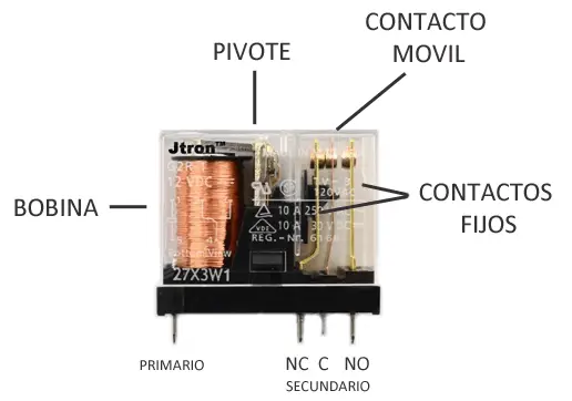
Relays usually have three contacts in the secondary circuit C (common), NO (normally open), and NC (normally closed). But we also find models that do without the NC terminal.
When the relay is activated, the current flows through the coil of the primary circuit, generating a magnetic field that pivots an armature, which in turn pushes the movable contact, closing the circuit with the NO fixed contact. Meanwhile, it separates and opens the circuit with the NC terminal.
When the current in the primary circuit ceases, the movable contact returns to its original position, opening the circuit with the NO terminal, and closing it with the NC terminal.
Therefore, to control the load with a relay as if it were a switch, we will always connect one of the poles to the C terminal (common), which is connected to the movable contact of the secondary.
The other pole of the load must be connected to one of the NO or NC terminals, depending on whether we want the circuit to close (load on) or open (load off) when the relay is activated.
- The NO (normally open) terminal is isolated from C when the relay is off and connected when the relay is on.
- The NC (normally closed) terminal is connected to C when the relay is off, and isolated when the relay is on.
Assembly diagram
If using a commercial board, the assembly is really simple. First, we power the module’s electronics Vcc and GND to Arduino’s Vcc and GND through the existing terminals.
On the other hand, we connect the load to the three-connection terminal block. We must always connect one of the load’s poles to the C terminal, which is usually the middle terminal.
The other pole of the load is connected to the NO or NC terminal, depending on whether we want the secondary to be open (NO) or closed (NC) when the relay is deactivated.
Finally, we connect the signal pin to a digital output of Arduino. If we use a board with multiple channels, we would connect each of the channels directly to a digital output.
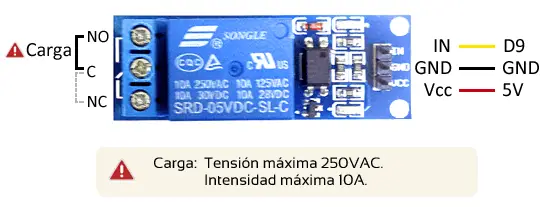
The connection, seen from Arduino, would be as follows.
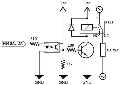
If you decide to do the entire assembly yourself, the electrical schematic is not complicated either. Arduino outputs do not have enough current to activate a relay, so we use an amplification stage as we saw in the BJT transistor entry.
We power this stage using a digital output, interposing an optocoupler to electrically isolate both circuits. We also add a flyback diode, which we also saw in the BJT transistor entry, since the primary of the relay is an inductive load.
Code examples
The necessary code is equally simple, and we only need to treat it like any other digital output, as we saw in the digital outputs entry.
For example, the following code simply turns the load on and off at 10-second intervals.
const int pin = 9;

void setup() {
  Serial.begin(9600);    //iniciar puerto serie
  pinMode(pin, OUTPUT);  //definir pin como salida
}

void loop(){
  digitalWrite(pin, HIGH);   // poner el Pin en HIGH
  delay(10000);               // esperar un segundo
  digitalWrite(pin, LOW);    // poner el Pin en LOW
  delay(10000);               // esperar un segundo
}Download the code
All the code from this post is available for download on Github.

