What is a rotary encoder?
A rotary encoder is a generic device that allows determining the angular position and speed of an actuator, and recording the measurement from a processor or controller like Arduino.
This is not the first time we talk about encoders and their utility. Previously we have seen optical encoders and magnetic encoders, as well as their importance when applying motor and actuator selection criteria.
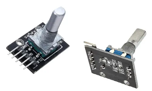
There are multiple types of rotary encoders, but in the scope of Arduino and DIY electronics projects, it is very common to find electromechanical rotary encoders.
Externally these encoders can be similar to certain types of potentiometer models, which can be an advantage because it makes certain accessories similar, and it may even be possible to replace one with the other.
However, a rotary encoder should not be confused with a potentiometer since both its electronics and behavior are completely different.
This type of rotary encoder is an incremental device that provides a digital pulse every time the encoder rotates a certain angle. The number of pulses per revolution depends on the encoder used, with 256 pulses/revolution being common.
Frequently, they also include a push button that activates when the encoder lever is pressed.
Interestingly, this type of encoders are not very useful for acting as encoders proper, that is, to record the rotation of an element (for example, a robot’s wheel) due to the difficulty of coupling it to the shaft and the low resolution of the encoder.
Their main use is as a control device or in place of potentiometers. For example, they can be used to adjust the brightness of an LCD screen, the volume of a device, or the angle of a stepper motor or servo.
Price
Encoders are inexpensive devices. We can find them in modules prepared to be easily connected to Arduino for €0.45 from international sellers on Ebay and Aliexpress.
We can also purchase the encoder separately as a component, without being integrated into a board. However, the price is practically the same, so in general, it is recommended to acquire it in a module.
How does a rotary encoder work?
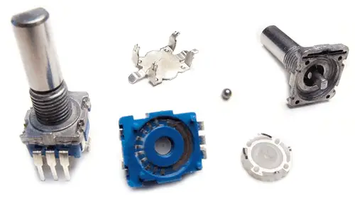
Internally, the encoder is formed by two brushes that slide on a metallic track with divisions. When the shaft rotates, a small metal ball closes the contact, acting as a push button.
To read the encoder, we must understand how to read a push button, as we saw in Read a push button with Arduino and Read a push button with Arduino using interrupts and debounce.
Normally, they have two outputs forming a system equivalent to having two push buttons (Channel A and B). These push buttons are offset from each other, forming what is called a quadrature encoder.
In a quadrature encoder, there is a phase shift between both sensors so that the signal they produce is shifted by 90º electrically. Graphically, the signal from both channels with respect to the rotated angle would be as follows.
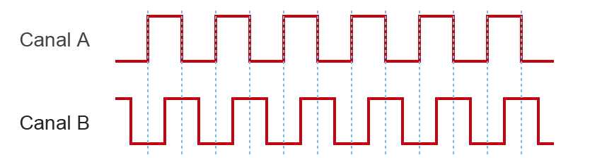
The advantage of quadrature encoders is that, in addition to detecting position and speed, they allow determining the direction of rotation.
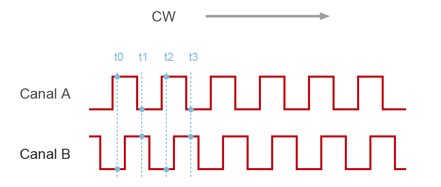
To visualize it, consider that we take the rising or falling edges of Channel A as the origin of events. If we rotate in the CW direction, events t0, t1, t2, t3… tn will occur.
If in these events we look at Channel B, we see that the signal from A is always the inverse of Channel B.
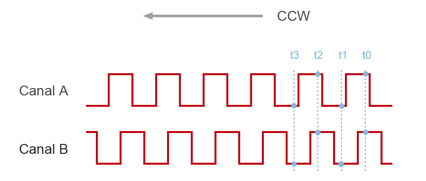
If we reverse the direction of rotation, and similarly take the rising or falling edges of Channel A as a reference, we see that at instants (t0, t1, t2, t3… tn) the signal from Channel A and B are always identical.
In reality, whether the direction of rotation is CW or CCW will depend on the internal construction of the sensor, the connection, and the channel we take as a reference.
But, in any case, we see that it is possible to differentiate the direction of rotation simply by comparing the signals obtained in the quadrature encoder, and assigning a physical meaning CW or CCW is immediate, simply by testing the assembly once.
Regarding the precision, we have more than one option.
- Single precision, recording a single edge (rising or falling) in a single channel.
- Double precision, recording both edges in a single channel.
- Quadruple precision, recording both edges in both channels.
Wiring diagram
To connect the encoder to Arduino, we need three digital inputs, two for detecting the encoder and an additional one if we want to record the lever press.
Ideally, we should use interrupts to record the encoder movement. Unfortunately, most Arduino boards only have two pins associated with interrupts. In the case of wanting quadruple precision, this means using the two pins with interrupts.
More information about interrupts on Arduino at What are and how to use interrupts on Arduino.
In this case, the encoder connection would be as follows.
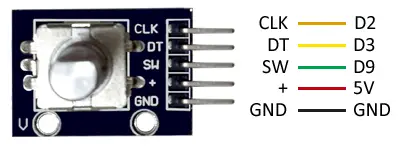
While the connection seen from Arduino would be as follows.
However, it is possible to use the encoder without using interrupts, which allows using digital inputs. However, we will have to check the input state by polling, which means worse performance.
In Arduino Uno, Nano, and Mini Pro, the interrupt pins are D2 and D3. For other Arduino models, consult the corresponding pinout diagram.
Code examples
Single or double precision by polling
In this first example, we read the encoder by polling, without using interrupts. To do this, we can use any two digital inputs, in the example D9 and D10. The precision can be double or single, for which you will have to change the commented line in the conditional (although I can’t think of a reason to prefer single precision over double)
const int channelPinA = 9;
const int channelPinB = 10;

unsigned char stateChannelA;
unsigned char stateChannelB;
unsigned char prevStateChannelA = 0;

const int maxSteps = 255;
int prevValue;
int value;

const int timeThreshold = 5;
unsigned long currentTime;
unsigned long loopTime;

bool IsCW = true;

void setup() {
  Serial.begin(9600);
  pinMode(channelPinA, INPUT);
  pinMode(channelPinB, INPUT);
  currentTime = millis();
  loopTime = currentTime;
  value = 0;
  prevValue = 0;
}

void loop() {
  currentTime = millis();
  if (currentTime >= (loopTime + timeThreshold))
  {
    stateChannelA = digitalRead(channelPinA);
    stateChannelB = digitalRead(channelPinB);
    if (stateChannelA != prevStateChannelA)  // For single precision if((!stateChannelA) && (prevStateChannelA))
    {
      if (stateChannelB) // B is HIGH, it's CW
      {
        bool IsCW = true;
        if (value + 1 <= maxSteps) value++; // Ensure we don't exceed maxSteps
      }
      else  // B is LOW, it's CCW
      {
        bool IsCW = false;
        if (value - 1 >= 0) value = value--; // Ensure we don't have negatives
      }

    }
    prevStateChannelA = stateChannelA;  // Save values for next

    // If the value has changed, display it
    if (prevValue != value)
    {
      prevValue = value;
      Serial.print(value);

    }

    loopTime = currentTime;  // Update time
  }

  // Other tasks
}
Double precision with one interrupt
In this example, we change one of the digital inputs for an interrupt, recording rising and falling edges, so we have double precision.
const int channelPinA = 2;
const int channelPinB = 10;

const int timeThreshold = 5;
long timeCounter = 0;

const int maxSteps = 255;
volatile int ISRCounter = 0;
int counter = 0;

bool IsCW = true;

void setup()
{
  pinMode(channelPinA, INPUT_PULLUP);
  Serial.begin(9600);
  attachInterrupt(digitalPinToInterrupt(channelPinA), doEncode, CHANGE);
}

void loop()
{
  if (counter != ISRCounter)
  {
    counter = ISRCounter;
    Serial.println(counter);
  }
  delay(100);
}

void doEncode()
{
  if (millis() > timeCounter + timeThreshold)
  {
    if (digitalRead(channelPinA) == digitalRead(channelPinB))
    {
      IsCW = true;
      if (ISRCounter + 1 <= maxSteps) ISRCounter++;
    }
    else
    {
      IsCW = false;
      if (ISRCounter - 1 > 0) ISRCounter--;
    }
    timeCounter = millis();
  }
}
Quadruple precision with two interrupts
In this last example, we use interrupts for both channels, and on both edges. We obtain quadruple precision, but in return we leave most Arduino models without additional interrupt pins.
const int channelPinA = 2;
const int channelPinB = 3;

const int timeThreshold = 5;
long timeCounter = 0;

const int maxSteps = 255;
volatile int ISRCounter = 0;
int counter = 0;

bool IsCW = true;

void setup()
{
  pinMode(channelPinA, INPUT_PULLUP);
  pinMode(channelPinB, INPUT_PULLUP);
  Serial.begin(9600);
  attachInterrupt(digitalPinToInterrupt(channelPinA), doEncodeA, CHANGE);
  attachInterrupt(digitalPinToInterrupt(channelPinB), doEncodeB, CHANGE);
}

void loop()
{
  if (counter != ISRCounter)
  {
    counter = ISRCounter;
    Serial.println(counter);
  }
  delay(100);
}

void doEncodeA()
{
  if (millis() > timeCounter + timeThreshold)
  {
    if (digitalRead(channelPinA) == digitalRead(channelPinB))
    {
      IsCW = true;
      if (ISRCounter + 1 <= maxSteps) ISRCounter++;
    }
    else
    {
      IsCW = false;
      if (ISRCounter - 1 > 0) ISRCounter--;
    }
    timeCounter = millis();
  }
}

void doEncodeB()
{
  if (millis() > timeCounter + timeThreshold)
  {
    if (digitalRead(channelPinA) != digitalRead(channelPinB))
    {
      IsCW = true;
      if (ISRCounter + 1 <= maxSteps) ISRCounter++;
    }
    else
    {
      IsCW = false;
      if (ISRCounter - 1 > 0) ISRCounter--;
    }
    timeCounter = millis();
  }
}
Download the code
All the code from this post is available for download on Github. 
