What is RS485?
RS485 is a widely used communication standard in industry that can be used with processors like Arduino to read from or write to other devices.
RS485 is simple, robust, and unlike other proprietary technologies, its use is free. For these reasons, many sensor and actuator devices have adopted it as a communication method, being common in the industrial field.
One advantage of RS485 is its long transmission distance. The range depends on the speed, making it possible to achieve 35 Mbps at distances of less than 10 meters, and up to 100 Kbps at distances up to 1200 meters.
RS485 is a physical layer protocol according to the OSI model. That is, it does not set rules or restrictions on the content, form, or encoding of the messages sent. Therefore, we can use it to send any type of signal, such as a digital signal, PWM, serial port, or I2C bus.
An RS485 bus has two conductors called A and B (inverted). Twisted pair cable is usually used to increase noise immunity. It is possible to access up to 32, 128, or 254 stations using a single twisted pair.
The protocol works simply by reversing the voltage between A (non-inverting) and B (inverting):
- When A+ and B- are considered to be in a LOW state.
- When A- and B+ are considered to be in a HIGH state.
With RS485, we can establish simplex, half-duplex, and full-duplex communication. However, for full-duplex communication, we will have to establish two different channels and have a receiver and transmitter at each terminal.
RS485 is often used in combination with UARTs to send signals over long distances. It is also common to find it as a physical layer in a Modbus protocol implementation.
RS485 projects include industrial plant automation. It is also used in automotive and even in airplanes for device connections. Other examples of use include building automation, monitoring of photovoltaic systems, or control of large lighting or sound systems such as music concerts.
Price
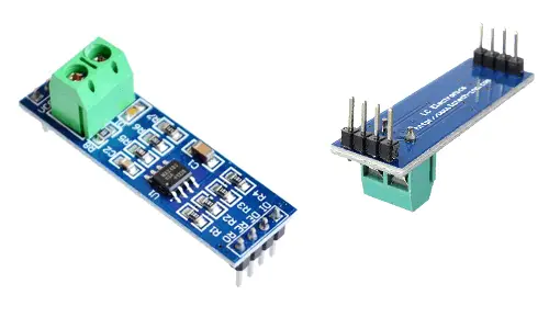
RS485 converters for Arduino, such as the MAX485, are very cheap devices. They can be found for €0.35, searching on international sellers like eBay or AliExpress.
Assembly scheme
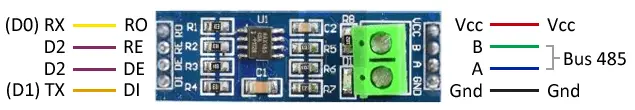
The connection of the modules with MAX485 is simple. First, we power the module by connecting Vcc and Gnd, respectively, to the 5V and Gnd of the Arduino.
On the other hand, we will have to connect the A and B conductors of the twisted pair that make up the RS485 bus, to which all devices belonging to the same bus will be connected.
Now, we must configure the module as a transmitter or receiver, for which we use the RE (receiver enable) and DE (driver enable) pins. If we connect these pins to Vcc, the module will act as a transmitter, and if we connect them to Gnd, it will act as a receiver.
Finally, we will have to connect the data input to the module DI (drive input) in the case of acting as a transmitter, or the data output of the module RO (receiver output) in the case of acting as a receiver.
Therefore, if we are using the UART of Arduino, the connection in transmitter mode is as follows,
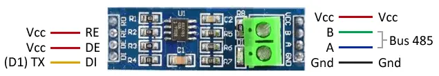
While the connection in receiver mode is as follows,
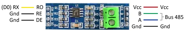
If we want the RS485 converter to be able to change its role from transmitter to receiver during the connection (half-duplex connection), we just have to connect the RE and DE pins to a digital output to be able to change its voltage from Gnd to Vcc.
In all cases, the Arduino connection is similar. The following image shows the half-duplex connection seen from Arduino.
Logically, if we are only going to act as a transmitter or receiver, we can do without one of the data pins (RX or TX) and the connection to the digital pin of RE/DE, permanently connecting them to Gnd or Vcc, respectively, as seen in the previous schemes for receiver and transmitter.
As we said before, if we want full-duplex communication (transmitter and receiver simultaneously), we will have to use two RS485 converters in each device and two independent parallel RS485 buses, one for TX and one for RX.
Code examples
RS485 is only a physical layer protocol, that is, a “transmission medium” through which we can send any digital signal, including UART, Modbus, SPI bus, I2C.
To connect to an RS485 device, such as a thermostat, a sensor, or an industrial actuator, we will need to know the protocol it uses and the frame (just as we do whenever we connect a device).
To illustrate its use, as an example, we are going to show the use of RS485 using the serial port. Therefore, all the examples we saw when looking at the use of the serial port in Arduino will be valid.
Simplex communication
The first example illustrates the operation of simplex mode, that is, in which each device has a fixed configuration. In the example, a transmitting Arduino sends a single byte to a receiving Arduino. In a real project, the transmitter or receiver could be any other device such as a sensor, an actuator, or even another processor or a computer like a Raspberry Pi.
The code is very simple, the transmitter sends a byte through the serial port, and the receiver captures it. In this case, we have taken millis()/1000 as an example, but it could be any other data, such as a sensor measurement, or a command to execute.
Transmitter code
void setup()
{
  Serial.begin(9600);
}

void loop()
{
  byte data = millis() / 1000;
  Serial.write(data);
  delay(250);
}
Receiver code
void setup()
{
  Serial.begin(9600);
}

void loop()
{
  if (Serial.available())
  {
    byte data = Serial.read();
  }
}
Half-duplex communication
The next example shows the half-duplex operation, that is, each Arduino can act as a transmitter or receiver, but not simultaneously. For this, we have a digital pin (pin 2 in the example) to change the mode of each Arduino. We also indicate the mode in which each Arduino is operating with the pin integrated on the board.
The example simulates the request for data from a leader Arduino to a follower Arduino. For this, the leader sends a simple frame, in this case a simple ‘H’. The follower responds by sending an integer variable, which is collected by the leader. In a real project, we could send different commands, or an address to communicate with several followers.
Leader code
const int ledPin = 13; // Integrated LED
const int ReDePin = 2; // HIGH = Driver / LOW = Receiver
const char HEADER = 'H';

void setup()
{
  Serial.begin(9600);
  Serial.setTimeout(100);

  pinMode(ledPin, OUTPUT);
  pinMode(ReDePin, OUTPUT);
}

void loop()
{
  // RS485 transmitter
  digitalWrite(ReDePin, HIGH);
  digitalWrite(ledPin, HIGH);
  Serial.print(HEADER);
  Serial.flush();
  delay(50);

  // RS485 as receiver
  digitalWrite(ReDePin, LOW);
  digitalWrite(ledPin, LOW);
  if (Serial.find(HEADER))
  {
    int data = Serial.parseInt();

    // Here we would do whatever we want with data
  }
}
Follower code
const int ledPin = 13; // Integrated LED
const int ReDePin = 2; // HIGH = Driver / LOW = Receiver
const char HEADER = 'H';

void setup()
{
  Serial.begin(9600);

  pinMode(ReDePin, OUTPUT);
  pinMode(ledPin, OUTPUT);
  pinMode(ReDePin, OUTPUT);
}

void loop()
{
  // RS485 as receiver
  digitalWrite(ReDePin, LOW);
  digitalWrite(ledPin, LOW);

  if (Serial.available())
  {
    if (Serial.read() == HEADER)
    {
      // RS485 transmitter
      digitalWrite(ReDePin, HIGH);
      digitalWrite(ledPin, HIGH);

      int data = millis() / 1000;
      Serial.print(HEADER);
      Serial.print(data);
      Serial.flush();
    }
  }
  delay(10);
}
