In this post we will learn the basic operation of serial ports in Arduino. Serial ports are the main way to communicate an Arduino board with a computer* or with another microcontroller.
Thanks to the serial port we can, for example, move the mouse or simulate user keyboard input, send email alerts, control a robot by performing calculations on the computer, turn a device on or off from a web page via the Internet, or from a mobile app via Bluetooth.
There are endless possibilities that require the use of the serial port!
Therefore, the serial port is a fundamental component of a large number of Arduino projects, and it is one of the basic elements we must learn to be able to unlock Arduino’s full potential.
At the end of the post I will provide several example codes, but first it is useful to briefly explain some theory about what a serial port is, and some terms we will need to correctly understand the operation of the serial port.
You can check the rest of the tutorials on the Arduino serial port, (receiving numbers, texts, comma-separated arrays, bytes, and many more) in the Arduino serial port category.
What is a serial port?
A port is the generic name we give to interfaces, physical or virtual, that allow communication between two computers or devices.
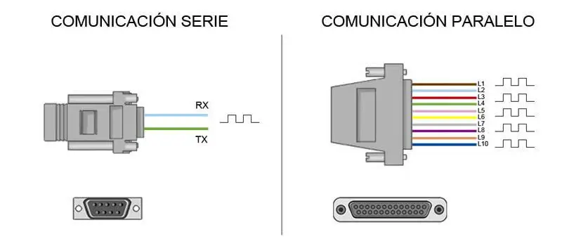
A serial port sends information via a sequence of bits. To do this, at least two connectors are needed for data communication, RX (reception) and TX (transmission) (however, there may be other conductors for voltage reference, clock synchronization, etc.).
In contrast, a parallel port would send information via multiple channels simultaneously. For this, they require a higher number of communication conductors, which vary depending on the type of port (similarly, there is the possibility of additional conductors besides the communication ones).
Historically, both types of ports coexisted in computers, with parallel ports being used in applications that required the transmission of larger volumes of data.
However, as processors became faster, serial ports progressively displaced parallel ports in most applications.
A conventional computer has several serial ports. The most well-known are the popular USB (Universal Serial Port) and the almost forgotten RS-232 (the one from old mice).
However, within the field of computing and automation there are a large number of additional types of serial ports, such as RS-485, I2C, SPI, Serial Ata, Pcie Express, Ethernet or FireWire, among others.
Sometimes you will see serial ports referred to as UART. The UART (universally asynchronous receiver/transmitter) is a unit incorporated into certain processors, responsible for converting data into a sequence of bits and transmitting or receiving them at a certain speed.
On the other hand, you may also hear the term TTL (transistor-transistor logic). This means that communication is carried out by signal variations between 0V and Vcc (where Vcc is usually 3.3V or 5V).
In contrast, other transmission systems use voltage variations from -Vcc to +Vcc (for example, RS-232 ports typically vary between -13V to 13V).
Before connecting two systems we must check that the voltages used are compatible. If they are not, we will need a subsystem that adapts the signal levels, or we may damage one of the devices.
Arduino and the serial port
Practically all Arduino boards have at least one UART unit. Arduino UNO and Mini Pro boards have one UART unit that operates at TTL level 0V / 5V, so they are directly compatible with USB connection. For their part, Arduino Mega and Arduino Due have 4 UART TTL 0V / 5V units.
Serial ports are physically connected to different pins on the Arduino board. Logically, while using the serial ports we cannot use the pins associated with the serial port in use as digital inputs or outputs.
| Arduino | Serial Port | Pin RX | Pin TX |
|---|---|---|---|
| Arduino UNO | Serial 0 | 0 (RX) | 1 (TX) |
| Arduino Mini Pro | Serial 0 | 0 (RX) | 1 (TX) |
| Arduino Mega | Serial 0 | 0 (RX) | 1 (TX) |
| Arduino Mega | Serial 1 | 19 (RX) | 18 (TX) |
| Arduino Mega | Serial 2 | 17 (RX) | 16 (TX) |
| Arduino Mega | Serial 3 | 15 (RX) | 14 (TX) |
| Arduino Due | Serial 0 | 0 (RX) | 1 (TX) |
| Arduino Due | Serial 1 | 19 (RX) | 18 (TX) |
| Arduino Due | Serial 2 | 17 (RX) | 16 (TX) |
| Arduino Due | Serial 3 | 15 (RX) | 14 (TX) |
Many Arduino board models have a USB or Micro USB connector connected to one of the serial ports, which simplifies the connection process with a computer. However, some boards, such as the Mini Pro, do without this connector, so the only way to connect to them is directly through the corresponding pins.
We should not get used to using the serial port if we don’t really need to communicate with the computer. The libraries used for serial port use occupy a considerable size, and we should only use them if we really need them. Furthermore, it unnecessarily disables the associated digital pins.
Connecting the Arduino to a computer
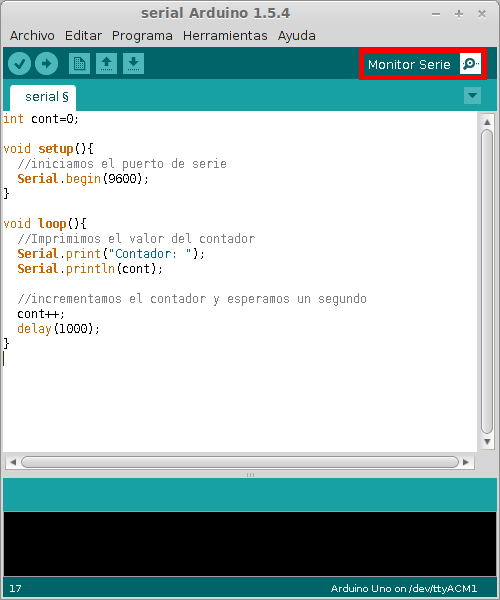
To connect via serial port, you only need to connect our Arduino board using the same port we use to program it. Then open the Arduino Standard IDE and click on the “Serial Monitor” as shown in the image.
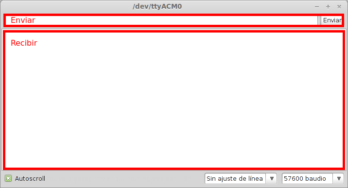
The serial monitor is a small utility integrated into the Standard IDE that allows us to easily send and receive information through the serial port. Its use is very simple, and it has two areas, one that shows received data, and another to send it. These areas are shown in the following image.
Despite its simplicity, this serial monitor is sufficient for the examples in this post, and is very useful for performing quick tests or experiments.
Example codes
Receiving information from the Arduino
In this first code we are going to receive the value of a counter sent from the Arduino board. This value increments every second. We can observe how the values are received from the serial monitor.
int cont=0;

void setup(){
  //initialize the serial port
  Serial.begin(9600);
}

void loop(){
  //Print the counter value
  Serial.print("Counter: ");
  Serial.println(cont);

  //increment the counter and wait a second
  cont++;
  delay(1000);
}
Sending information to the Arduino
In this example we use the serial port to turn the integrated LED on the Arduino board on or off. To do this, we send a character to the Arduino board, using the serial monitor. If ‘a’ is sent, the Arduino board turns the LED off, and if ‘b’ is sent, it turns it on.
int option;
int led = 13;

void setup(){
  Serial.begin(9600);
  pinMode(led, OUTPUT);
}

void loop(){
  //if data is available, read it
  if (Serial.available()>0){
    //read the sent option
    option=Serial.read();
    if(option=='a') {
      digitalWrite(led, LOW);
      Serial.println("OFF");
    }
    if(option=='b') {
      digitalWrite(led, HIGH);
      Serial.println("ON");
    }
  }
}
Sending numeric values
Finally, in this example we send a number from 1 to 9 through the serial monitor, and the Arduino board makes the integrated LED blink the indicated number of times. The code is similar to the previous one, but it is noted that since the data is sent as ASCII characters, we must subtract the value ‘0’ from the received data to recover the sent numeric value.
int option;
int led = 13;

void setup(){
  Serial.begin(9600);
  pinMode(led, OUTPUT);
}

void loop(){
  //if there is pending information
  if (Serial.available()>0){
    //read the option
    char option = Serial.read();
    //if the option is between '1' and '9'
    if (option >= '1' && option <= '9')
    {
      //subtract the value '0' to get the sent number
      option -= '0';
      for(int i=0;i<option;i++){
         digitalWrite(led, HIGH);
         delay(100);
         digitalWrite(led, LOW);
         delay(200);
      }
    }
  }
}
That’s it for the basic examples. However, the serial port is not the only means of communication in Arduino. Other important communication systems between devices are the SPI bus and the I2C bus.
Update 10/11/2015: The new Arduino IDE v1.6.6 includes a tool for making graphs with the values received from the serial port, called “Serial Plotter”. You can see more about its use in the post Easily make graphs with Arduino IDE V1.6.6.
Download the code
All the code from this post is available for download on Github. 
