What is a Solid State Relay?
A Solid State Relay or SSR (Solid State Relay) is a semiconductor-based device with behavior similar to a conventional relay, which we can use with a processor like Arduino to switch large loads, even AC loads at 220V.
Let’s remember that a conventional relay is a device that uses a movable terminal actuated by a coil to make an electrical contact in a secondary circuit. This allows controlling large loads from a low-power primary circuit, compatible with control electronics.
Instead, a solid state relay uses semiconductor-based electronic components. Because it lacks moving parts, a solid state relay has certain advantages over a conventional relay.
The main advantage is a faster switching speed. A conventional relay has a typical response time of 0.2s to 2s depending on its size. With a solid state relay, we can achieve switching times on the order of ms.
The other big advantage is durability. A conventional relay experiences wear and tear from the movement of its parts, leading to failure after a number of on/off cycles. A solid state relay has no moving parts, so it does not suffer from this wear and tear problem.
Other advantages include smaller size, silent operation, no risk of sparking (inflammable environments), lower electrical noise, greater environmental immunity (humidity, vibrations, electromagnetic interference).
As disadvantages, they generally have a higher price than the conventional equivalent, for the same characteristics, that is, nominal voltage and maximum permissible current.
On the other hand, the load supported by the solid state relay results in a series of losses that manifest as heat dissipation. For large loads, it will be necessary to add a heat sink.
Finally, despite its fast response time, we cannot use a PWM signal to regulate the intensity of the AC load (for example, regulating the speed of a motor or the intensity of a light).
Solid state relays can be a substitute for conventional relays, which, as we know, hold a prominent place in our electronic, home automation, and Internet projects, as they allow us to control almost any device from a processor like Arduino.
For example, we can turn on a fluorescent tube from a mobile phone, turn the boiler on or off by acting on the thermostat, deploy an awning or lower a blind, turn on a watering system, activate or deactivate external hard drives, among countless applications.
Price
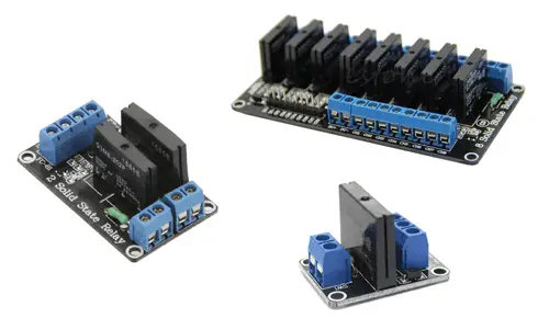
In home electronics, we find various modules with solid state relays designed to connect to Arduino. There are versions with one or more channels, each channel consisting of an optocoupled SSR, with a maximum voltage of 240VAC and a maximum permissible current of 2A.
Thus, we have modules with one channel for 1.65, two channels for 3.25€, four channels for 6.15, and eight channels for 10.70€, searching on international sellers on eBay or AliExpress.
These modules, although cheap and easy to use, have low electrical characteristics. If preferred, we can use a normal solid state relay. For example, we can find a solid state relay for voltages of 24-380VAC and currents of up to 40A for 3.20€.
These relays are a bit more expensive and bulky than those used in modules prepared for Arduino, but in return, they have much superior characteristics.
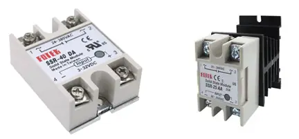
These relays are also optocoupled and have protection to ensure that the activation always occurs on the rising edge.
How does a Solid State Relay work?
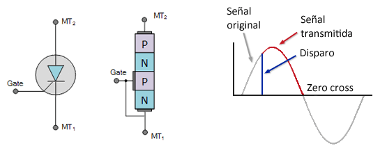
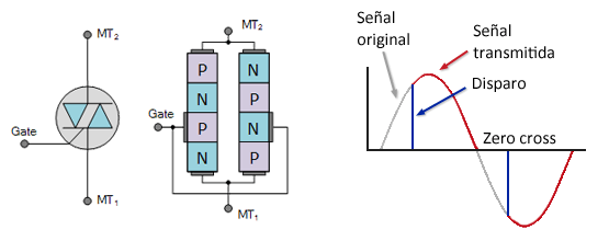
The main component of a relay is a triac, an electronic component that is in turn based on thyristors. Both elements are widely used in power electronics.
A thyristor has behavior similar to a diode, as it only allows current to pass in one direction. However, similar to a MOSFET transistor, the conduction state is controlled by a Gate terminal.
In short, a thyristor:
- Starts conducting when the Gate is put under tension and the signal is positive.
- Remains conducting even if we remove the Gate voltage (latching).
- Stops conducting when the signal passes through zero (zero-crossing) and the Gate is deactivated.
To take advantage of this behavior with alternating current, we have triacs, which are essentially two thyristors in opposite directions sharing a common Gate terminal.
The behavior is similar to a thyristor, except that in a triac, conduction can occur in both the positive and negative half-cycles of the AC signal.
Latching, or the fact that thyristors and triacs conduct even if the Gate voltage is removed, remaining until the signal passes through zero, has important consequences when handling AC loads.
The first is that the activation time is very fast, as it is only conditioned by the activation time of the SRR, which is in the order of us.
However, deactivation depends on the state of the AC signal and can be as long as 1/(2* f(Hz)), a half-period. In the case of AC at 50Hz, the time can be up to 10ms.
Another consequence is the inability to regulate an AC load using PWM. The reason is that the PWM signal triggers are not synchronized with the AC current, activating the SSR at different points in the AC signal.
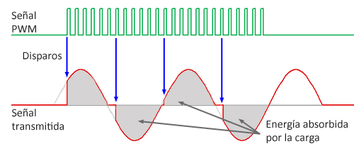
Since the triac conducts until the zero crossing, each half cycle, the load receives a different amount of energy, causing random flickering instead of regulating the load.
To generate a regulator for AC loads (a dimmer), we must add a zero-crossing detection integrated circuit to synchronize the SSR control signal with the AC signal.
Finally, it should be noted that in solid state relays, the triacs are always optocoupled to achieve galvanic isolation of the high-power secondary stage from the low-power primary control stage.
Connection Diagram
The connection diagram is very simple. First, we connect the load to the connection terminal. Remember that for the load, the relay behaves similarly to a switch, so in most cases, you will only need to insert the relay into one of the poles of the load to turn it on or off.
On the other hand, we power the module’s electronics by connecting DC+ and DC- to 5V and Gnd on Arduino, respectively. Finally, connect the CH1 signal pin to any digital output on Arduino. If you have a relay with more than one channel, simply connect each pin to a digital output.
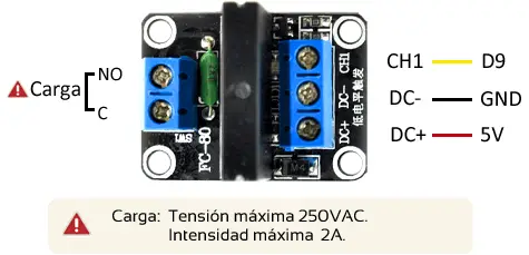
The connection, seen from Arduino, would be as follows.
Code Examples
The required code is equally simple, and we only need to treat it like any other digital output as we saw in the digital outputs entry.
For example, the following code simply turns the load on and off in 10-second intervals.
const int pin = 9;

void setup()
{
  Serial.begin(9600);    //start serial port
  pinMode(pin, OUTPUT);  //define pin as output
}

void loop()
{
  digitalWrite(pin, HIGH);   // set the pin to HIGH
  delay(10000);             // wait for ten seconds
  digitalWrite(pin, LOW);    // set the pin to LOW
  delay(10000);             // wait for ten seconds
}
Download the Code
All the code in this post is available for download on Github. 
