In this post, we will look at the SPI bus, one of the main communication methods available in Arduino. In previous posts we already saw the serial port, and in the next post we will see the I2C bus.
The SPI bus is interesting as a communication medium because a wide variety of commercial sensors and devices feature an SPI interface as a means of communication.
The SPI Bus
The SPI bus (Serial Peripheral Interface) was developed by Motorola in 1980. Its advantages over other systems have made it a de facto standard in the world of electronics and automation.
The SPI bus has a master-follower architecture. The master device can initiate communication with one or more follower devices, and send or receive data from them. Follower devices cannot initiate communication, nor exchange data directly among themselves.
In the SPI bus, data communication between masters and followers is carried out on two independent lines, one from the master to the followers, and another from the followers to the master. Therefore, the communication is Full Duplex, meaning the master can send and receive data simultaneously.
Another characteristic of SPI is that it is a synchronous bus. The master device provides a clock signal, which keeps all devices synchronized. This reduces system complexity compared to asynchronous systems.
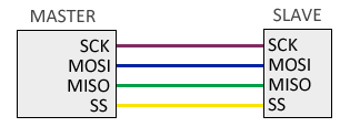
Therefore, the SPI bus requires a minimum of 3 lines.
- MOSI (Master-out, follower-in) for communication from master to follower
- MISO (Master-in, follower-out) for communication from follower to master
- SCK (Clock) clock signal sent by the master
Additionally, an additional SS (Follower Select) line is required for each connected follower device, to select the device with which communication will take place.
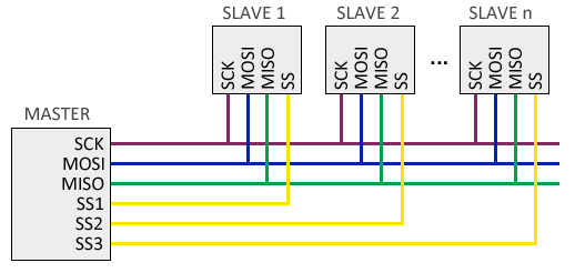
However, this has the disadvantage of requiring one line per follower device. In case of having many follower devices this may not be practical, so it is possible to adopt a cascade connection, where each follower transmits data to the next.
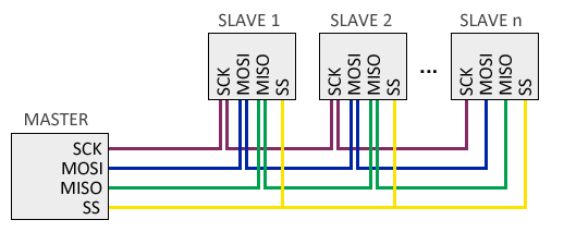
On the other hand, in this configuration the information must reach all followers for the communication to be finalized, so, in general, the bus response speed is lower.
How the SPI Bus Works|t179390
The operation of the SPI bus is simple.
By default, the master keeps all SS lines in a HIGH state. When the master wants to establish communication with a follower, it sets the corresponding SS line to LOW, which indicates to the follower that it should start communication.
On each pulse of the clock signal, usually on the rising edge, the master device sends a bit to the follower and simultaneously receives a bit from the selected follower.
The frame (the data sent) does not follow any rule, meaning we can send any arbitrary sequence of bits. This means that connected devices need to have pre-agreed upon the length and meaning of what they are going to send and receive.
The electronics required to implement the SPI bus are simple and cheap, even a single shift register can be enough. Furthermore, since the clock signal is provided by the master, followers don’t even need to have their own clock.
Advantages and Disadvantages of SPI
The SPI Bus in Arduino
Hardware
Arduino has hardware SPI support physically linked to certain pins. It is also possible to use any other group of pins as an SPI bus via software, but in that case the speed will be much lower.
The pins associated with SPI vary from one model to another. The following table shows the arrangement in some of the main models. For other models, consult the corresponding pinout diagram.
| MODEL | SS | MOSI | MISO | SCK |
|---|---|---|---|---|
| Uno | 10 | 11 | 12 | 13 |
| Nano | 10 | 11 | 12 | 13 |
| Mini Pro | 10 | 11 | 12 | 13 |
| Mega | 53 | 51 | 50 | 52 |
The hardware SS pin is used when using Arduino as a follower. When using Arduino as a master, we can use any pin as SS, or several if we have multiple followers.
Connecting the SPI bus is simple. Almost the biggest difficulty will be finding the function of each pin on the device we want to connect, because not all manufacturers use the same designation for the pins that participate in the SPI bus.
To make it easier for you, the following table shows some of the common pins you will find on SPI devices with designations you may encounter depending on the manufacturer. Those marked in red are power, in yellow are the SPI bus itself, and in blue are other pins that frequently appear on SPI devices, although they are not part of the SPI bus.
| Name | Alias | Pin (on Arduino Uno or Nano) | Description |
|---|---|---|---|
| VCC | +3.3 … 5 Volt | ||
| GND | Ground | Ground | |
| SCLK | CLK/SCK/SCLK | D13 (hardware) | Clock (SPI) |
| MISO | MISO/SDO/DOUT | D12 (hardware) | Master In Follower Out (SPI) |
| MOSI | MOSI/SDI/DIN | D11 (hardware) | Master Out Follower In (SPI) |
| SS | SS/CS/SDA/ | D10 (hardware, only in follower) | Follower/Chip Select (SPI) |
| RES | RST/RES/REST | D9 (variable, set by software) | Controller Reset |
| RS | RS/DC | D8 (variable, set by software) | Mode: Command/Data |
Software
To use the SPI port in Arduino the Standard IDE provides the “SPI.h” library which contains the necessary functions to control the integrated SPI hardware.
Likewise, the Arduino programming environment defines the constants SCK, MOSI, MISO, and SS for the SPI pins. Using these “aliases” in our code makes it easier to exchange programs between board models.
The basic functions to operate the SPI bus are as follows:
SPI.begin();            // Starts the SPI bus
SPI.transfer(c);        // Sends a byte
SPI.attachInterrupt();  // Activates the interrupt to receive data
Other functions are also available to configure SPI bus options. To change the order of the bits sent, we have the setBitOrder function:
setBitOrder (LSBFIRST);   // least significant bit first
setBitOrder (MSBFIRST);   // most significant bit first
To change the clock polarity and phase we have the SPI.setDataMode function:
setDataMode (SPI_MODE0);  // clock normally LOW, sampling on rising edge
setDataMode (SPI_MODE1);  // clock normally LOW, sampling on falling edge
setDataMode (SPI_MODE2);  // clock normally HIGH, sampling on rising edge
setDataMode (SPI_MODE3);  // clock normally HIGH, sampling on falling edge
Finally, we can change the bus speed with the SPI.setClockDivider() function with divisors from 2 to 128. The bus frequency will be the clock speed divided by the chosen divisor.
setClockDivider(SPI_CLOCK_DIV2);   //8 MHz (considering a 16 MHz model)
setClockDivider(SPI_CLOCK_DIV4);   //4 MHz
setClockDivider(SPI_CLOCK_DIV8);   //2 MHz
setClockDivider(SPI_CLOCK_DIV16);  //1 MHz
setClockDivider(SPI_CLOCK_DIV32);  //500 KHz
setClockDivider(SPI_CLOCK_DIV64);  //250 KHz
setClockDivider(SPI_CLOCK_DIV128); //125 KHz
However, these functions have been obsolete since Arduino version 1.6.0., preferring the beginTransaction function, as shown in the following example.
SPI.beginTransaction (SPISettings (2000000, MSBFIRST, SPI_MODE0)); // 2 MHz clock, MSB first, mode 0
Nevertheless, since the data frame is specific to each device, it is most common that we do not use these functions directly, and our use of the SPI bus is done indirectly through the component’s library.
In upcoming posts, we will see how to connect two Arduinos via I2C port, and introduce the I2C bus.
Download the Code
All the code from this post is available for download on Github. 
