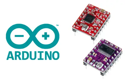
What is A4988 or DRV8825?
The A4988 and the DRV8825 are controllers (drivers) that simplify the handling of stepper motors from an automaton or processor such as Arduino.
These controllers allow us to manage the high voltages and intensities required by these motors, limit the current flowing through the motor, and provide protections to prevent damage to the electronics.
For their control, they only require two digital outputs, one to indicate the direction of rotation and the other to communicate that we want the motor to advance one step. They also allow for microstepping, a technique for achieving precision greater than the nominal step of the motor.
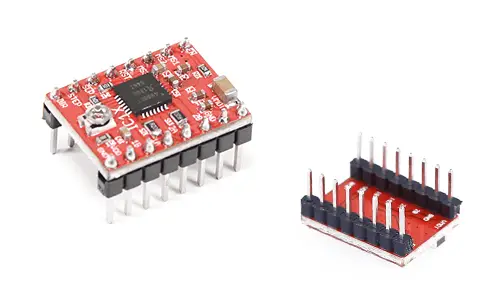
The A4988 has gained great popularity in recent times due to its use in projects such as, for example, in homemade 3D printers. On the other hand, the DRV8825 is an improved version of the A4988 and, therefore, has slightly superior characteristics.
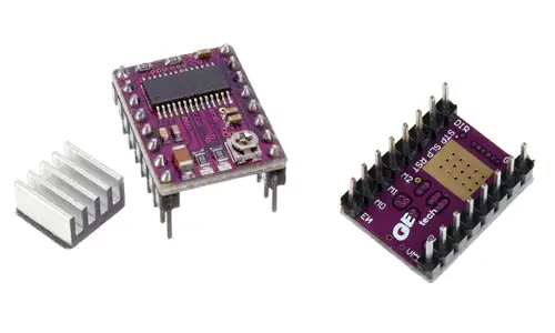
In particular, the DRV8825 allows working with higher voltages than the A4988 (45V versus 35V), and higher intensities (2.5A versus 2A). In addition, it adds a new microstepping mode (1/32) that is not present in the A4988.
Otherwise, apart from some minor differences, both devices are similar in their assembly and use. They can even be compatible with each other, that is, under certain conditions we can use one or the other interchangeably, or even a combination of both simultaneously.
| Model | A4988 | DRV8825 |
|---|---|---|
| Color | Green or Red | Purple |
| Maximum Intensity | 2A | 2.5A |
| Maximum Voltage | 35V | 45A |
| Microsteps | 16 | 32 |
| Typical Rs | 0.05, 0.1, 0.2 | 0.1 |
Both controllers can reach high temperatures during operation and it is necessary to dissipate the heat so that the device is not damaged. For intensities greater than 1A in the A4988 and 1.5A in the DRV8825, it is necessary to add a heat dissipation system, or even forced ventilation.
They have protections against overcurrent, short circuit, overvoltage, and overtemperature. In general, they are robust and reliable devices as long as we make the connection correctly and incorporate heat dissipation if necessary.
The A4988 and the DRV8825 are widely used in a variety of projects that require the use of stepper motors, such as CNC machines, plotters, drawing robots, 3D printers, and 3D scanners.
They are also a common component in projects to control robots and vehicles, especially those that require varying the speed of each wheel individually, such as vehicles with omniwheel or mecanum wheels.
Price
Currently, both controllers are inexpensive devices as their price has decreased due to the increase in their popularity. It is possible to find an A4988 driver for 0.75€, and a DRV8825 for 1.15€, from international sellers on eBay or AliExpress.
With such a small price difference, it is normal to choose the DRV8255, given that it has superior technical characteristics.
How does the A4988 and the DRV8825 work?
As in most motor controllers, the fundamental component is an H-bridge. In the case of the A4988 and DRV8825, designed to control stepper motors, there are two H-bridges (one per channel) consisting of MOSFET transistors.
However, unlike simpler controllers such as the L298N or the TB6612FNG, which have relatively simple electronics, the A4988 and the DRV8825 have considerably more complex electronics.
For example, in the following image, we have the schematic of the DRV8255 and, as we can see, the H-bridges (highlighted in blue) represent a very small part of the whole.
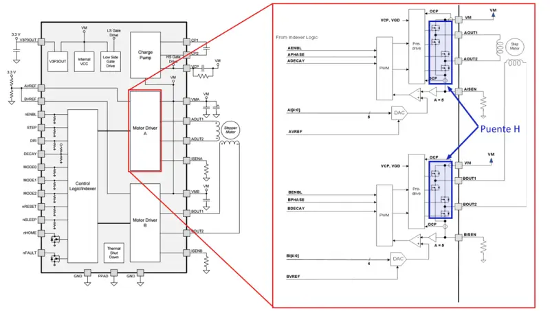
One of the reasons for this complexity is that they only require two digital control signals to operate the motor and incorporate the necessary protections for handling.
The other reason for the complexity of their electronics is that they incorporate functions specially designed for the control of stepper motors, such as the current regulator and the Microstepping. We will see these functionalities below.
Current Regulation (Chopping)
Both controllers have built-in current regulators. The reason is that stepper motors of a certain size and power, such as the NEMA 17 or NEMA 23, require voltages higher than those that the coils could support by their nominal current.
For example, suppose we have a NEMA 17 motor with a nominal intensity of 1.2A and 1.5 Ohm of resistance per phase. According to Ohm’s law, we should apply 1.8V to each coil for the nominal intensity of 1.2A to flow. However, with that voltage, the motor would not move.
For the motor to work correctly, we need to apply a higher voltage. In this example, the nominal voltage could be 12V. But if we applied 12V directly, again by Ohm’s law, 8A would pass through the coil, which would destroy the motor in a short time.
For this reason, the controllers incorporate a current limiter, which allows the motor to be supplied with nominal voltages higher than those possible by its resistance and maximum allowable intensity.
Of course, Ohm’s law must be satisfied at all times, so continuing with our example, when we power the motor at 12V, inevitably 8A will pass through the coil.
The limiter interrupts the signal by providing a pulsed PWM signal so that the average value of the current flowing through the coil is the nominal intensity of the motor. Finishing our example, the voltage limiter would apply the pulse during 15% of the time and keep the motor off for the remaining 85%.
This intensity limitation mechanism is called Chopping.
To regulate the intensity provided by the limiter and adjust it to the value of the motor we are going to use, both boards have a potentiometer that regulates the intensity of the limiter.
One way to estimate the intensity of the regulator is to measure the voltage (Vref) between the potentiometer and GND and apply a formula that depends on the model, which you will find in the table at the beginning of the entry.
These formulas depend on the value Rs of the resistors located on the board that can vary depending on the manufacturer. The typical values also appear in the table, but you should check the value of the resistors on your board.
For example, with the usual values of Rs, the formulas are reduced to:
| Model | Rs | Reduced Formula |
|---|---|---|
| A4988 | 50 | I_max = 0.625 * V_ref |
| A4988 | 100 | I_max = 1.25 * V_ref |
| A4988 | 200 | I_max = 2 , 2* V_ref |
| DRV8825 | 100 | I_max = 2 * V_ref |
However, the value obtained by this measurement is only an approximation and may be inaccurate, so we will use it only as an initial calibration, and we will finish the fine-tuning by measuring the actual current provided by the controller to the motor using an ammeter.
Microstepping
As we mentioned, microstepping is a technique that allows obtaining steps smaller than the nominal step of the stepper motor that we are going to control.
When we saw the typical sequences of a step-by-step ignition, we saw that by applying an all-or-nothing control to the coils, we had several possible combinations, of which we saw the three most common (1-phase, 2-phases, half-phase). But no one said that we have to completely turn the coils on or off.
Microstepping varies the current applied to each coil, emulating an analog value. If we could apply two perfect sinusoidal electrical signals to both coils, 90 degrees out of phase, we would achieve a perfect rotating magnetic field inside the motor.
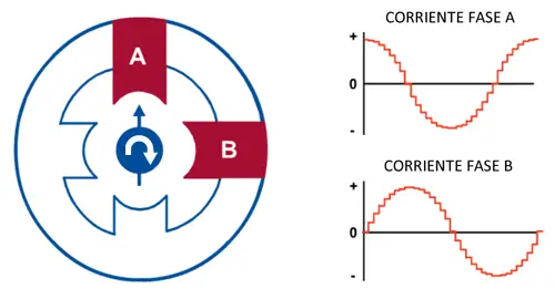
Of course, the digital controller does not generate perfect analog values, but discretized (“stepped”) values, so the electrical signal it applies is also a discretized sinusoidal function.
The result is a rotating magnetic field with a step smaller than the nominal step, depending on the number of discrete levels that we can use in the coil excitation signals.
When we work without microstepping (Full step mode), the controllers apply a 2-phase sequence, so they permanently apply 71% of the current of the limiter to each coil. They only vary the direction in which the current flows through the coil.
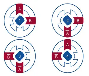
However, if we apply microstepping in any of its operating modes, the controller reaches 100% of the current to one of the coils in a certain step. The specific amount of current applied to each coil varies with each step.
For example, with a 1/4 step resolution, in the first step of the sequence, we will have one coil at 100% and coil B at 0%, in the second step coil A at 92% and coil B at 38%, in the third step coil A at 71%, and so on.
The fact that without microstepping the applied current is always 71%, and if we apply microstepping (at any resolution) the applied current will reach 100% in some step, is very important when calibrating the current flowing through the coils.
Finally, the resolution with which we want the controller to work is controlled by applying voltage to the M0, M1, and M2 Pins. These pins are pulled to ground by Pull-Up resistors, so if we do not connect anything, they will be Low, and we only need to force the pins to High.
| Resolution | M0 | M1 | M2 |
|---|---|---|---|
| Full step | Low | Low | Low |
| 1/2 step | High | Low | Low |
| 1/4 step | Low | High | Low |
| 1/8 step | High | High | Low |
| - | Low | Low | High |
| - | High | Low | High |
| 1/16 step | High | High | High |
Leaving all pins disconnected will result in using Full Step mode.
Assembly Diagram
The connection diagram of both controllers is very similar. Even, as we have said, under certain considerations, both devices are compatible with each other.
In the case of the A4988, the scheme is as follows
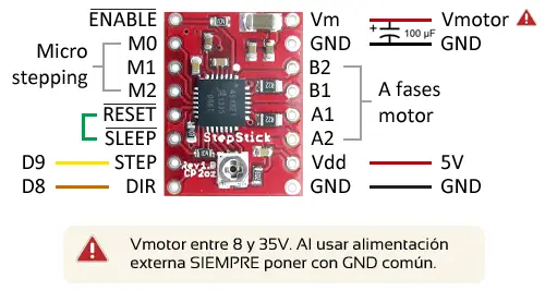
Seen from Arduino, it would look like this.
In the case of the DRV8825, the scheme is very similar, with the exception that the Vdd pin is replaced by the ¬Fault pin.
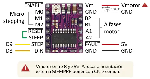
The scheme from Arduino would be identical to the previous one.
Check the orientation of the controller during assembly and before powering the system.
Assembly Process
The assembly process of the A4988 or the DRV8825 is not too complicated. The only part that is a bit tricky is the process of adjustment and calibration of the current regulator.
Both controllers are quite robust and difficult to break when they are working, if we respect the heat dissipation needs (when necessary).
But they are extremely sensitive to disconnecting the motor when the controller is powered. Doing this will almost certainly damage the controller.
In general, avoid connecting or disconnecting any cable while the controller is powered.
On the other hand, the potentiometer of the current regulator has no physical stop, so it is possible to go from zero to the maximum value without realizing it, and we could accidentally damage the motor.
To avoid damaging the controller or the component, we must always follow the process rigorously without skipping any steps.
- Connect the driver to voltage, without the motor and without microstepping
- Measure the voltage between GND and the potentiometer with a voltmeter
- Adjust the potentiometer until the voltage is the value provided by the formula
- Turn off the assembly
- Connect the motor, interposing an ammeter
- Carefully make the fine adjustment of the potentiometer, until the current is the motor’s nominal value
- Turn off the assembly
- Remove the ammeter, and connect the motor permanently
- Connect Arduino to the assembly
As we have said, the fact that we are going to use microstepping later influences the limit value that we must set in the current regulator.
If we are not going to use Microstepping, we can increase the limit of the current regulator to 100% of the motor’s nominal intensity.
If we are going to use Microstepping, the value we have measured is 71% of what will actually flow through the coil. Therefore, in the ammeter, we must adjust the 71% of the motor’s nominal intensity.
Code Example
Although understanding the details of A4988 and DRV8825 may have been difficult, the advantages of their use are clear. The code required for their control is extremely simple, which makes them very practical and useful components to use.
We just have to indicate through two digital outputs the moment when we want the motor to advance one step, and the direction of rotation. The speed of rotation is controlled by the time we let pass between steps.
The following example rotates the stepper motor one revolution in one direction and two revolutions in the opposite direction at a slightly higher speed.
const int dirPin = 8;
const int stepPin = 9;

const int steps = 200;
int stepDelay;

void setup() {
  // Mark the pins as output
  pinMode(dirPin, OUTPUT);
  pinMode(stepPin, OUTPUT);
}

void loop() {
  //Activate a direction and set the speed with stepDelay
  digitalWrite(dirPin, HIGH);
  stepDelay = 250;
  // Rotate 200 pulses to make a complete turn
  for (int x = 0; x < steps * 1; x++) {
    digitalWrite(stepPin, HIGH);
    delayMicroseconds(stepDelay);
    digitalWrite(stepPin, LOW);
    delayMicroseconds(stepDelay);
  }
  delay(1000);

  //Change direction and increase speed
  digitalWrite(dirPin, LOW);
  stepDelay = 150;
  // Rotate 400 pulses to make two complete turns
  for (int x = 0; x < steps * 2; x++) {
    digitalWrite(stepPin, HIGH);
    delayMicroseconds(stepDelay);
    digitalWrite(stepPin, LOW);
    delayMicroseconds(stepDelay);
  }
  delay(1000);
}
Download the Code
All the code from this post is available for download on Github. 
