What is the ESP8266?
The ESP8266 is a low-cost microprocessor with integrated WiFi manufactured by Espressif. We can use the ESP8266 to connect our electronics and robotics projects with Arduino.
Before the ESP8266, the available options to connect an Arduino to WiFi (such as the WiFi Shield) were prohibitively expensive. The emergence of the ESP8266 was a small revolution as it was the first really cheap device that provided WiFi connectivity.
In reality, the ESP8266 is much more than a WiFi module for Arduino. It is a complete processor, with much more power than most Arduino models. In fact, it is one of the main “competitors” that Arduino faces.
There are many models of boards that integrate the ESP8266, and a growing community of users around this processor. We will extensively cover more details and models with ESP8266 in the section of advanced tutorials.
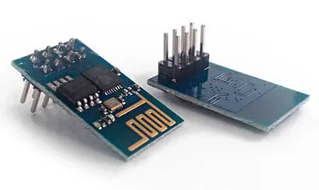
For now, in this post we will limit ourselves to using Arduino together with an ESP01 module, one of the first to appear with the ESP8266 chip and one of the simplest and cheapest modules.
The ESP01 mounts the simplest version of the ESP8266. Still, it remains a 32-bit processor at 80 Mhz, with 512kB or 1MB of memory depending on the model. It has 2 GPIO pins, SPI, I2C, and UART.
Regarding WiFi communication, the ESP01 has integrated 802.11 b/g/n communication, including Wi-Fi Direct (P2P) and soft-AP modes. It includes a complete TCP/IP stack, which relieves most of the communication work from the processor.
We can use the ESP01 to provide WiFi connectivity to our Arduino projects. However, as we mentioned with the Ethernet modules, communication with the Internet can be too much of a burden for Arduino.
If you require intensive use of the Internet, you should consider other alternatives such as Raspberry Pi, Orange Pi, or even the ESP8266 itself.
Price
ESP8266 modules of the ESP01 type are very cheap, as we have said, this is one of the reasons for their wide success. We can find them for 1.65€ from international sellers on eBay or AliExpress.
Assembly scheme
Connecting an ESP01 module to Arduino is not complicated, although in practice there may be certain difficulties that will finally make us consider the suitability of using it with Arduino, or opting for a solution based on ESP8266.
The main difficulty is the power supply of the ESP01. The ESP8266 and, in particular, the ESP01, has a power supply voltage of 3.3V. Under no circumstances can it be powered at a voltage higher than 3.6V, or we will damage the module.
On the other hand, the module’s consumption can exceed 200mA, especially during connection and startups. However, the 3.3V voltage regulator of Arduino can only provide 50mA (150mA in some models), which is insufficient to power the ESP01.
Therefore, we will need to power the ESP01 with an external 3.3V source. Otherwise, we will experience continuous cuts and crashes during its operation, which can also reduce the life of the ESP01.
The rest of the connection has no difficulty. On one hand, we have the CH_PD pin that turns the module on or off by connecting it, respectively, to Gnd or 3.3V. On the other hand, the RST pin resets the module if it is connected to Gnd. In some versions of the module, we can leave it unconnected, but in general, we will have to connect it to 3.3V for the module to start.
Finally, the communication with the module is done via serial port. Unlike the module’s power supply, which in no case should exceed 3.6V, there is a wide debate about whether the RX and TX pins are tolerant to 5V (i.e., if they can be connected directly to a 5V system).
In principle, connecting RX and TX to a 5V system does not seem to immediately damage the board. In fact, we find indications in the documentation that suggest they could be tolerant to 5V, without being completely clear. However, it is also not clear if it could reduce the life of the component.
In this post, we will connect the RX and TX pins directly. However, if you want total security, you should connect a 3.3V to 5V level adapter to the RX and TX pins.
For the connection with Arduino, we can use the normal serial port, but this implies that we will have to disconnect the ESP01 when we want to program Arduino, and we will not be able to use the serial port for communication with the PC.
For this reason, a software serial port is often used. However, keep in mind that this means a significant processing load for Arduino.
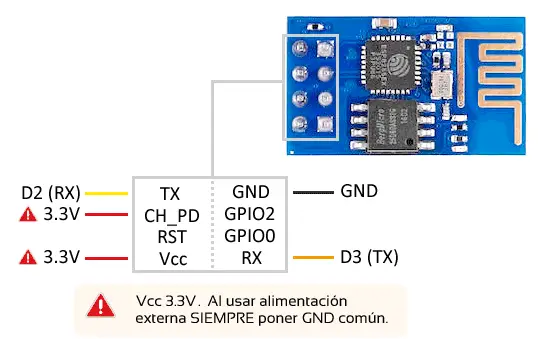
In the schemes of this post, we assume that we are using a software serial port with TX on digital pin 2 and RX on digital pin 3, but we could define the port on any other I/O pin.
Therefore, the connection seen from Arduino would be as follows.
As for the speeds, the ESP01 can be set to 9600, 19200, 38400, 74880, 115200, 230400, 460800, and 921600. By default, they usually come, depending on the manufacturer, at 9600 or 115200.
If we are going to use Arduino as an intermediary, we will avoid speeds of 115200 and above because communication can become unstable and errors may appear.
Code examples
Using the ESP8266 with AT commands
Communication with the ESP01 with the default firmware is done through AT commands, which are simply text commands sent by Serial.
We can send these commands through a USB-TTL converter (FT232, CH340G, or CP2102) or, in our case, using Arduino and Software serial as an adapter.
First test
Let’s make the first connection test with the ESP01. To do this, we connect the ESP01 to Arduino as we have seen in the previous section. We leave Arduino connected to the computer via USB.
Next, we load the following Sketch in Arduino, which some will probably recognize as the Serial Loop program. This sketch only acts as a “bridge” between the hardware serial port connected to the PC and the soft serial port connected to the ESP01.
// The speed depends on the ESP-01 model
// being common 9600 and 115200
const int baudRate = 9600;

#include "SoftwareSerial.h"
SoftwareSerial softSerial(2, 3); // RX, TX

void setup()
{
  Serial.begin(baudRate);
  softSerial.begin(baudRate);
}

void loop()
// send the data from the serial console to the ESP-01,
// and show what was sent by the ESP-01 in our console
{
  if (softSerial.available())
  {
    Serial.print((char)softSerial.read());
  }
  if (Serial.available())
  {
    softSerial.print((char)Serial.read());
  }
}
Once the Sketch is loaded, we turn on (or restart) the ESP01. In the Serial Monitor, the ESP01 responds with a series of characters that depend on the manufacturer and model, and finally “Ready”, indicating that the module is ready.
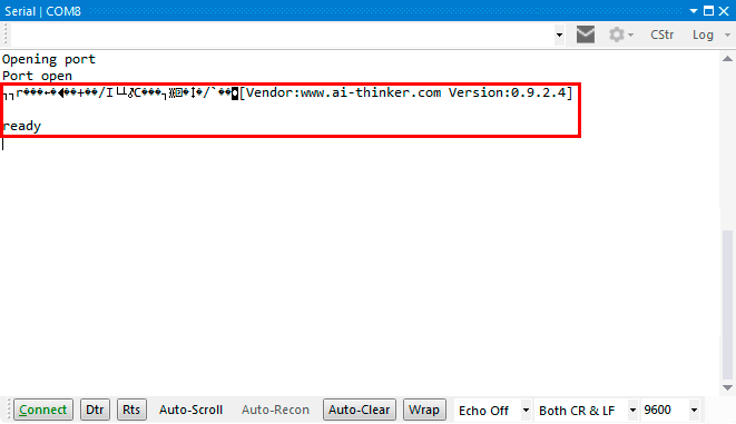
If we now write AT, the module will respond with “OK”, indicating again that the module is ready for use.
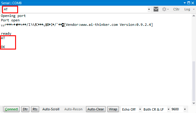
If you do not see the initial message ending in “Ready” and instead see “weird characters”, change the speed of the Serial Port in the Serial Loop Sketch and in the Serial Monitor.
List of AT commands
Next, a list of some of the AT commands available for the ESP8266.
//**** GENERAL ****
// Acknowledge, receives "ok"
AT

// Reset, restarts the module.
// Receives a text string that depends on the model and manufacturer and, at the end, "READY"
AT+RST

//**** CONFIGURATION ****
// Get the transmission speed
AT+CIOBAUD?

// Change the transmission speed (in the example to 9600)
// Valid speeds 9600, 19200, 38400, 74880, 115200, 230400, 460800 and 921600
AT+CIOBAUD=9600
AT+IPR=9600

// Get the operation mode
// 1 Station
// 2 SoftAp
// 3 Station + SoftAp
AT+CWMODE?

// Change the operating mode to 1, 2, or 3
// Normally AT+CWMODE=3, because it is the most versatile
// After the change, AT+RST is necessary
AT+CWMODE=mode

//**** CONNECT TO A WIFI NETWORK ****
// List Access Point
// Shows a list of available WiFi networks
AT+CWLAP

// Join Access Point
// Join an existing WiFi network
AT+CWJAP=you ssid, password

// Check if connected successfully, or use AT+CWJAP=?, or use AT+CIFSR to find your IP address
AT+CWJAP?

// Get the module's IP
AT+CIFSR

//**** CREATE A WIFI NETWORK ****

// Create a WiFi network
AT+CWSAP="ssid","password",3,0

// List the devices connected to the generated network
AT+CWLIF

//**** TCP SERVER ****
// Set up a TCP server on port 80 (1 means activated)
AT+CIPSERVER=1,80

//**** TCP CLIENT ****
// Enable multiple connections
AT+CIPMUX=1

// Connect to the remote server 192.168.1.100 on port 80
AT+CIPSTART=4,"TCP","192,168.1.100",80

// Set the transmission mode
AT+CIPMODE=1

// Send data through channel 4 (in the example 5 bytes)
AT+CIPSEND=4,5
AT Examples
Here are some simple examples to perform basic actions with the ESP01 through AT commands.
// List WiFi networks and connect to one of them
// replace SSID and PASSWORD with the network's parameters
AT+CWLAP
AT+CWJAP=SSID,PASSWORD

// Establish connection as a client
AT+CWJAP=SSID,PASSWORD
AT+CIPMUX=1
AT+CIPSTART=4,"TCP","google.com",80

// Establish a connection as a server
establish a server
AT+CWJAP=SSID,PASSWORD
AT+CIPMUX=1
AT+CIPSERVER=1,80
For example, to configure the ESP01 from an Arduino to act as a server, we would pass the AT commands as follows.
#include "SoftwareSerial.h"
SoftwareSerial softSerial(2, 3); // RX, TX

const int baudRate = 9600;
char* SSDI = "yourWifi";
char* password = "yourPassword";

void setup()
{
  Serial.begin(baudRate);
  softSerial.begin(baudRate);
  delay(1000);

  softSerial.write("AT+CWJAP=\"");
  softSerial.write(SSDI);
  softSerial.write("\",\"");
  softSerial.write(password);
  softSerial.write("\"\r\n");

  delay(4000);
  softSerial.write("AT+CIPMUX=1\r\n");
  delay(2000);
  softSerial.write("AT+CIPSERVER=1,80\r\n");
}

void loop()
{
  if (softSerial.available())
  {
    Serial.print((char)softSerial.read());
  }
  if (Serial.available())
  {
    softSerial.print((char)Serial.read());
  }
}
Using the ESP8266 with a library
There are several libraries that facilitate the use of the ESP8266 together with Arduino, although they are not very common since in general it is preferred to program the ESP8266 itself. These libraries use the same AT commands we have seen previously and manage the received responses, saving us the work.
One of the most complete is the ITEADLIB Arduino WeeESP8266 library, available at this link.
If we want to use the library with software serial it is necessary to enter the ESP8266.h file and uncomment the line.
#define ESP8266_USE_SOFTWARE_SERIAL
Other suggested improvements for using the ESP8266 with Arduino are to increase the size of the hardware serial or software serial buffer, for which it is necessary to edit the file
\arduino\hardware\arduino\avr\cores\arduino\HardwareSerial
or
\arduino\hardware\arduino\avr\cores\arduino\SoftwareSerial
and modify the following line.
// In HardwareSerial.h

#define SERIAL_BUFFER_SIZE 64

// In SoftwareSerial.h

#define _SS_MAX_RX_BUFF 64 // RX buffer size
Although, personally, I do not recommend modifying the buffer size. If the buffer size is too short, it is because you should process the data on the ESP01 itself, or use another machine, but not modify the buffer size.
WiFi Client - Read web pages
In this example, Arduino also acts as a client, that is, it connects to a web page to read it. Reading a complete page and dumping it through the serial port is very slow, and is one of the demonstrations of the limitations of Arduino compared to a computer.
However, it can be useful for Arduino to capture information from a server. For example, we can make it synchronize the time, read a series of parameters from a text file, perform a certain action if a file exists, etc.
To demonstrate this capability of reading data from a server on the Internet, we will use www.pasted.co, one of many web pages that allow us to add text to share with more people.
On the page http://www.pasted.co/2434bc64, I have pasted the text 1.2.3.4.5. The ’~’ will be used as separators to find the desired text ‘1.2.3.4.5’, which simulates a series of parameters that we want to capture from a server.
The following example connects to this address and searches for the text 1.2.3.4.5, which it shows through the serial port. In a real example, we would use these values, for example, to control a robot, change the measurement parameters of a station, turn a device on or off, etc.
#include "ESP8266.h"
#include <SoftwareSerial.h>

const char* SSID = "myssid";
const char* PASSWORD = "mypassword";
const char* HOST_NAME = "www.pasted.co";
const int HOST_PORT = 80;

SoftwareSerial softSerial(2, 3); // RX, TX
ESP8266 wifi(softSerial);

void setup(void)
{
  Serial.begin(9600);

  if (wifi.setOprToStationSoftAP()) {
    Serial.print("to station + softap ok\r\n");
  }
  else {
    Serial.print("to station + softap err\r\n");
  }

  if (wifi.joinAP(SSID, PASSWORD)) {
    Serial.print("Join AP success\r\n");
    Serial.print("IP:");
    Serial.println(wifi.getLocalIP().c_str());
  }
  else {
    Serial.print("Join AP failure\r\n");
  }

  if (wifi.disableMUX()) {
    Serial.print("single ok\r\n");
  }
  else {
    Serial.print("single err\r\n");
  }

  Serial.print("setup end\r\n");
}

void loop(void)
{
  uint8_t buffer[800] = { 0 };

  if (wifi.createTCP(HOST_NAME, HOST_PORT)) {
    Serial.print("create tcp ok\r\n");
  }
  else {
    Serial.print("create tcp err\r\n");
  }

  char *request = "GET /2434bc64 HTTP/1.1\r\nHost: www.pasted.co\r\nConnection: close\r\n\r\n";
  wifi.send((const uint8_t*)request, strlen(request));

  uint32_t len = wifi.recv(buffer, sizeof(buffer), 10000);
  if (len > 0)
  {
    Serial.print("Received:\r\n");
    for (uint32_t i = 0; i < len; i++)
    {
      char c = (char)buffer[i];
      if (c == '~')
      {
        for (uint32_t j = i + 1; j < len; j++)
        {
          c = (char)buffer[j];
          if (c == '~') break;
          Serial.print(c);
        }
        break;
      }
    }
    Serial.print("\r\n");
  }

  while (1) delay(1000);
}
WiFi Server - Handling requests
In this example, we configure the ESP01 module to act as a Web server, that is, to receive requests via WiFi and respond to them.
#include "ESP8266.h"
#include <SoftwareSerial.h>

const char* SSID = "myssid";
const char* PASSWORD = "mypassword";

SoftwareSerial softSerial(2, 3); // RX, TX
ESP8266 wifi(softSerial);


void setup(void)
{
  Serial.begin(9600);
  Serial.print("setup begin\r\n");

  wifi.restart();
  delay(500);

  if (wifi.setOprToStationSoftAP()) {
    Serial.print("to station + softap ok\r\n");
  }
  else {
    Serial.print("to station + softap err\r\n");
  }

  if (wifi.joinAP(SSID, PASSWORD)) {
    Serial.print("Join AP success\r\n");
    Serial.print("IP: ");
    Serial.println(wifi.getLocalIP().c_str());
  }
  else {
    Serial.print("Join AP failure\r\n");
  }

  if (wifi.enableMUX()) {
    Serial.print("multiple ok\r\n");
  }
  else {
    Serial.print("multiple err\r\n");
  }

  if (wifi.startTCPServer(80)) {
    Serial.print("start tcp server ok\r\n");
  }
  else {
    Serial.print("start tcp server err\r\n");
  }

  if (wifi.setTCPServerTimeout(10)) {
    Serial.print("set tcp server timout 10 seconds\r\n");
  }
  else {
    Serial.print("set tcp server timout err\r\n");
  }

  Serial.println("setup end\r\n");
}

void loop(void)
{
  uint8_t buffer[128] = { 0 };
  uint8_t mux_id;

  uint32_t len = wifi.recv(&mux_id, buffer, sizeof(buffer), 100);
  if (len > 0) {
    Serial.print("Received from: ");
    Serial.print(mux_id);
    Serial.print("\r\n");
    for (uint32_t i = 0; i < len; i++) {
      Serial.print((char)buffer[i]);
    }
    Serial.print("\r\n");

    if (wifi.releaseTCP(mux_id)) {
      Serial.print("release tcp ");
      Serial.print(mux_id);
      Serial.println(" ok");
    }
    else {
      Serial.print("release tcp");
      Serial.print(mux_id);
      Serial.println(" err");
    }

    Serial.print("Status: ");
    Serial.print(wifi.getIPStatus().c_str());
    Serial.println();
  }
}
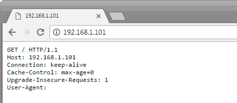
If you enter the local IP address assigned to the ESP01 into a web browser, you’ll see that the ESP8266 “serves” a webpage, which is nothing more than the content of the request issued by the browser (actually part of the request).
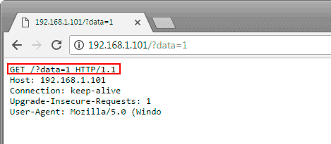
If we modify the request, for instance, by adding GET parameters, we’ll see that the ESP8266 receives the parameters through the URL of the request. This can be used to perform actions on the server side, as we’ll see in the next entry.
WiFi Server - Controlling Digital Outputs
In this Arduino example, the Arduino also acts as a server, but this time we want the user to be able to perform actions on Arduino through the served webpage.
#include "ESP8266.h"
#include <SoftwareSerial.h>

const char* SSID = "myssid";
const char* PASSWORD = "mypassword";

SoftwareSerial softSerial(2, 3); // RX, TX
ESP8266 wifi(softSerial);

void setup(void)
{
  pinMode(LED_BUILTIN, OUTPUT);

  Serial.begin(9600);
  Serial.print("setup begin\r\n");

  wifi.restart();
  delay(500);
  if (wifi.setOprToStationSoftAP()) {
    Serial.print("to station + softap ok\r\n");
  }
  else {
    Serial.print("to station + softap err\r\n");
  }

  if (wifi.joinAP(SSID, PASSWORD)) {
    Serial.print("Join AP success\r\n");
    Serial.print("IP: ");
    Serial.println(wifi.getLocalIP().c_str());
  }
  else {
    Serial.print("Join AP failure\r\n");
  }

  if (wifi.enableMUX()) {
    Serial.print("multiple ok\r\n");
  }
  else {
    Serial.print("multiple err\r\n");
  }

  if (wifi.startTCPServer(80)) {
    Serial.print("start tcp server ok\r\n");
  }
  else {
    Serial.print("start tcp server err\r\n");
  }

  if (wifi.setTCPServerTimeout(20)) {
    Serial.print("set tcp server timout 20 seconds\r\n");
  }
  else {
    Serial.print("set tcp server timout err\r\n");
  }

  Serial.println("setup end\r\n");
}


#define wifiWrite(A) wifi.send(mux_id, (uint8_t*) A, sizeof(A) - 1);
void loop(void)
{
  uint8_t buffer[128] = { 0 };
  uint8_t mux_id;

  uint32_t len = wifi.recv(&mux_id, buffer, sizeof(buffer), 100);
  if (len > 0) {
    Serial.print("Received from: ");
    Serial.print(mux_id);
    Serial.print("\r\n");

    wifiWrite("HTTP/1.1 200 OK\r\nnContent-Type: /html\r\nConnection: close\r\n\r\n");
    wifiWrite("<html>\n<head>\n<title>Luis Llamas</title>\n</head>\n<body>");
    wifiWrite("<h2>Salidas digitales</h2>");
    wifiWrite("<button onClick=location.href='./?data=0'>ON</button>");
    wifiWrite("<button onClick=location.href='./?data=1'>OFF</button>");
    wifiWrite("</body></html>");

    Serial.println("Send finish");

    for (uint32_t i = 0; i < len; i++) {
      char c = (char)buffer[i];
      if (c == '?')
      {
        if ((char)buffer[i + 6] == '1')
        {
          digitalWrite(LED_BUILTIN, HIGH);
          Serial.println("LED ON");
        }
        else
        {
          digitalWrite(LED_BUILTIN, LOW);
          Serial.println("LED OFF");
        }

        break;
      }
    }
  }
}
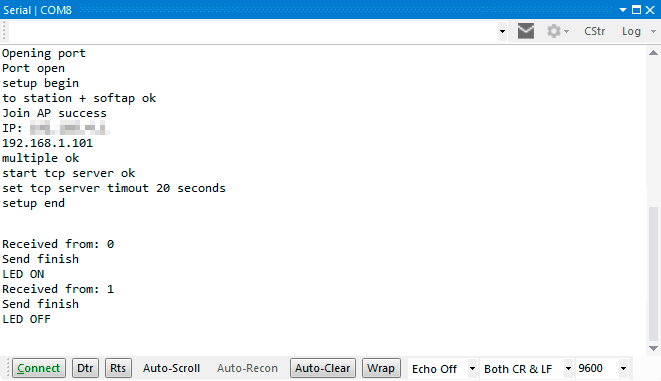
For this purpose, we serve a webpage with two buttons, which will allow turning on or off the LED integrated in Arduino. The extension of the page that we can serve is quite small, but, as we have repeated several times, if you have to serve complex pages, you should probably consider using the ESP8266 independently or using another machine.
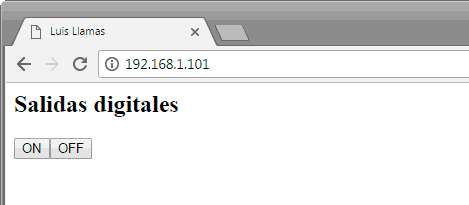
By clicking on the corresponding buttons, the requested URL has the parameter ‘?data=0’ or ‘?data=1’. These parameters are obtained through the URL of the request, using the ’?’ character as a separator.
Depending on whether the character after ‘?data=’ is ‘0’ or ‘1’, the integrated LED is turned on or off, and the action is shown on the serial port.
Descarga el código
Todo el código de esta entrada está disponible para su descarga en Github. 
