What is a Wiichuck?
The Wiichuck, or Wii Nunchuk, is an additional controller for the Wii console. The controller uses the I2C bus, making it easy to connect this controller to a PLC or processor like Arduino to have a great controller for our projects.
The Wiichuck is a small technological gem. It integrates a three-axis LIS3L02AL accelerometer, a 2-axis analog joystick, and two buttons in a single small and ergonomic device. Being a device manufactured in large quantities has made it available at low prices.
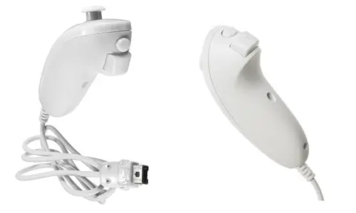
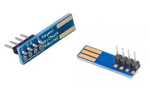
The Nunchuk is connected to the primary Wii controller via a cable. We can cut this cable and connect it to Arduino or, much more conveniently, use available PCB modules that are inserted into the Wiichuck connector and allow it to be connected without damaging it.
The Wii Nunchuk is a great controller to add to our projects. For example, we can use it to control a turret with servos, operate a robotic arm, a vehicle, a hexapod, or a bipedal robot.
Price
The Wii Nunchuk is an excellent controller in terms of price and performance. We can find them for €3 from international sellers on eBay or AliExpress.
As for the Wiichuck connection module with Arduino, we can find it for €0.60. For that price, it’s worth saving the work of cutting and soldering the cable, in addition to avoiding damaging the Wiichuck.
Assembly diagram
If we use an adapter, the connection is very simple. We insert the module into the Wii controller, and we power it by connecting Vcc and Gnd, respectively, to 3.3V and Gnd on Arduino.
On the other hand, we will use the I2C bus pins on Arduino to establish communication with the Wiichuck. We simply connect the SDA and SCL pins of Arduino to the corresponding pins on the Wii Nunchuk.
Therefore, the connection is as follows,
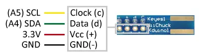
Which viewed from the Arduino side would look like this.
If we choose not to buy the adapter and connect directly to the controller, we will have to connect cables to the controller, either by cutting and soldering its conductor or by inserting terminals into the connector. The following diagram shows the pinout of the WiiChuck connector.
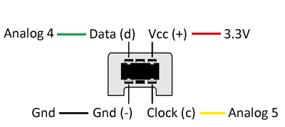
On Arduino Uno, Nano, and Mini Pro, SDA is pin A4 and SCK is pin A5. For other models of Arduino, check the corresponding pinout diagram.
The Wii controller operates at 3.3V. Powering it at higher voltages (such as 5V) will damage the controller.
Code examples
To read the Wii Nunchuk, we will use the library developed by jnw.walker and updated by coopermaa available at this link.
The library provides code examples, which it is advisable to review. For example, the following code shows the values read from the WiiChuck
//GND - GND
//VCC - VCC
//SDA - Pin A4
//SCL - Pin A5

#include <Wiichuck.h>
#include <Wire.h>

Wiichuck wii;

void setup() {
  Serial.begin(9600);
  wii.init();
  wii.calibrate();
}

void loop() {
  if (wii.poll()) {
    Serial.print("joy:");
    Serial.print(wii.joyX());
    Serial.print(", ");
    Serial.print(wii.joyY());
    Serial.print("  \t");

    Serial.print("accle:");
    Serial.print(wii.accelX());
    Serial.print(", ");
    Serial.print(wii.accelY());
    Serial.print(", ");
    Serial.print(wii.accelZ());
    Serial.print("  \t");

    Serial.print("button:");
    Serial.print(wii.buttonC());
    Serial.print(", ");
    Serial.print(wii.buttonZ());
    Serial.println("");
  }

  delay(100);
}
Download the code
All the code from this post is available for download on Github. 
