
What is an H11AA1?
The H11AA1 is a zero crossing detector, a device that emits a pulse when a voltage signal passes through 0V. Of course, we can connect a zero crossing detector to a processor like Arduino.
When working with alternating current, such as the distribution network (230V 50Hz), it is often interesting to detect the instant when the voltage crosses the zero point. Thus, for example, it is a simple way to measure the grid frequency. It is also possible to rectify the angular phase shift introduced by transformers used when measuring the voltage.
Another frequent use is to determine the moment to switch a load, for example, using a relay or a solid state relay. Loads should be connected and disconnected only when the voltage crosses zero in the upward direction. Otherwise, we would be making the connection with the load under voltage, which causes the generation of harmonics and, possibly, the reduction of the components’ lifespan.
Zero crossing detectors like the H11AA1 are also necessary to perform power regulation (dimmer) with an SSR, for example, to regulate the intensity of a light bulb or the speed of a motor. It is necessary to synchronize the SSR trigger signal with the grid frequency, or apply a time delay between the zero crossing and the trigger, or we will cause flickering in the load.
Industrially, zero crossing detectors are widely used in applications that run on alternating current, both for measurements and for actions. They are also common components in sound and communication systems.
We can use it in our projects, for example, for measuring the frequency of electrical distribution grid, voltage measurement with a transformer, consumption monitoring, to improve the switching behavior of a relay, or to make a dimmer with a solid state relay.
Price
Zero crossing detectors like the H11AA1 are very cheap devices. We can find them for €0.25 from international sellers on eBay or AliExpress.
How does the H11AA1 work?
In the entry using an optocoupler with Arduino we extensively saw these devices that allow transmitting information from one circuit to another using light, maintaining galvanic isolation between circuits. We then anticipated that there were various types of optocouplers, with more uses.
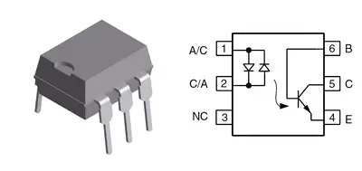
The H11AA1 is a bidirectional optocoupler, consisting of two GaAr LEDs along with an NPN phototransistor in a single 6-pin DIP package. When either LED emits light, the phototransistor is in conduction. It will only be in cutoff when both LEDs are off.
Therefore, the H11AA1 allows us to connect an alternating current on the primary side. The secondary side will act as a closed switch except when the voltage on the primary side is lower than a voltage close to 0V, which will act as an open switch.
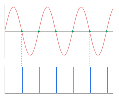
Combined with the H11AA1 with a pull-up resistor, we can generate a pulse when the primary side voltage is close to 0V, which allows us, among other things, to detect when an alternating voltage passes from the negative half-cycle to the positive half-cycle.
Assembly scheme
The assembly scheme is very simple. On the one hand, we connect the signal in which we want to detect the zero crossings to the A/C and C/A terminals, which control the optocoupler’s LEDs. We must add series resistors that limit the current passing through the LEDs.
We must adjust the value of these resistors to the voltage we are using. We saw how to calculate this value in the entry Connect a LED with Arduino. For example, for a 230VAC voltage, we can use a 2W resistor between 22K-47K.
On the other hand, we connect the secondary to any digital input of Arduino. If we use the internal pull-up resistor, we will not need any additional components to connect the secondary to Arduino.
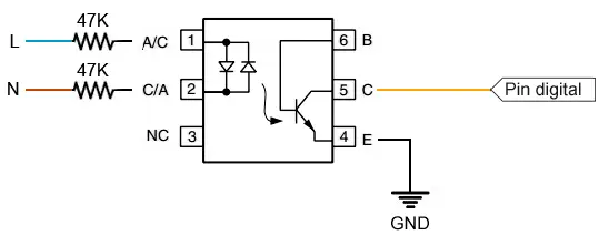
We can use any digital input, but in most cases, we will want to use an interrupt to perform the detection. The connection, seen from Arduino, would be as follows.
Code examples
Read state by pool
In the first example, we learn to read the state of the H11AA1 with Arduino’s digital inputs, as if it were a push button.
const int inputPin = 2;

int value = 0;

void setup() {
  Serial.begin(9600);
  pinMode(inputPin, INPUT_PULLUP);
}

void loop(){
  value = digitalRead(inputPin);  //digital pin read

  //send message to serial port based on the value read
  if (value == HIGH) {
      Serial.println("On");
  }
  else {
      Serial.println("Off");
  }
  delay(1000);
}
Measure frequency with interruption
In this example, we read the H11AA1 using interruptions, and measure the frequency between pulses.
// period of pulse accumulation and serial output, milliseconds
const int inputPin = 2;
const int MainPeriod = 100;
long previousMillis = 0; // will store last time of the cycle end

volatile unsigned long previousMicros=0;
volatile unsigned long duration=0; // accumulates pulse width
volatile unsigned int pulsecount=0;

// interrupt handler
void freqCounterCallback()
{
  unsigned long currentMicros = micros();
  duration += currentMicros - previousMicros;
  previousMicros = currentMicros;
  pulsecount++;
}

void reportFrequency()
{
    float freq = 1e6 / float(duration) * (float)pulsecount;
    Serial.print("Freq:");
    Serial.print(freq);
    Serial.println(" Hz");

     // clear counters
    duration = 0;
    pulsecount = 0;
}

void setup()
{
  Serial.begin(19200);
  pinMode(inputPin, INPUT_PULLUP);
  attachInterrupt(digitalPinToInterrupt(inputPin), freqCounterCallback, RISING);
}

void loop()
{
  unsigned long currentMillis = millis();
  if (currentMillis - previousMillis >= MainPeriod)
  {
    previousMillis = currentMillis;
    reportFrequency();
  }
}
Download the code
All the code from this post is available for download on Github. 
