We continue with the series of posts aimed at building a 2WD robot car controlled by a processor like Arduino.
In the previous post, we saw the budget and that we could build a fully functional robot for between 20-25€, depending on the accessories we want to add.
In this post, we will see the assembly of our 2WD robot car. In the next post in this series, we will see the electrical diagram, and in the last post, we will see some code examples.
2WD Robot Configuration
In the previous post, we saw that there were several configurations that we could assemble in our 2WD robot. Basically, all of them consist of a chassis with 2 motors and 2 wheels + a caster, along with a motor controller and a processor like Arduino.
The difference will be (apart from using another chassis) the processor we use, the motor controller, and the sensors or controls we want to add.
So, we remember that we had the option to put encoders to control the speed and position, which was practically essential if we wanted to control our 2WD robot correctly.
As for distance sensors, we could use ultrasonic, infrared, or laser sensors. The number of sensors varied, or if we preferred to put a single sensor attached to a servo so that it can rotate.
And another improvement was to put two or more line detectors, or a detection bar with several sensors, to make a line-following robot.
In this post, the configuration we are going to see is Arduino Nano, L298N motor controller, encoders, and a front-facing ultrasonic sensor HC-SR04. This is one of the simplest and most common configurations in “home-made” robots.
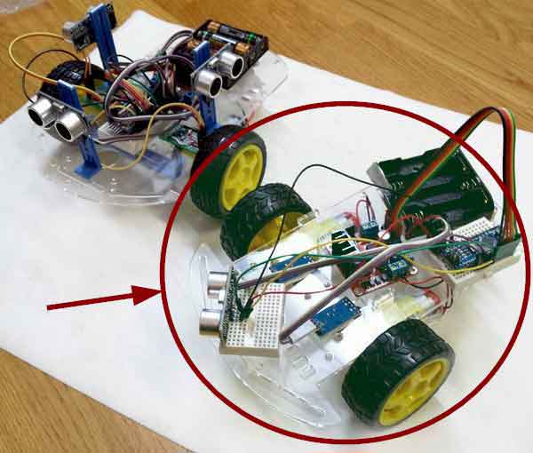
That is, from the following image, we are going to assemble the robot on the right (which in the image is half assembled while I was taking the photos, which is why you will see that certain parts are not “straight”).
In any case, making small modifications such as adding more distance sensors, or a servo to turn a sensor, or adding line detection, is very simple and has no difficulty.
Therefore, feel free to experiment and make the modifications you consider appropriate. That’s what we’re here for, to play and try!
2WD Robot Assembly
We start by soldering the cables to the motors. We will use black and red cables, for consistency, although this is not critical here because we do not know the direction of rotation of the motor yet. We can change it later in the L298N, or even in the code.
What is important is that, whatever criterion we take, we use the same one for both motors.
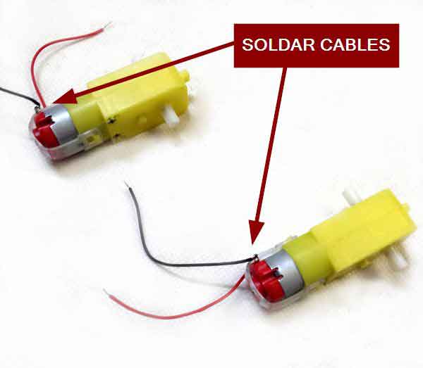
A soldering iron is a machine that can burn and be dangerous. Use it with care, and always in the presence of an adult.
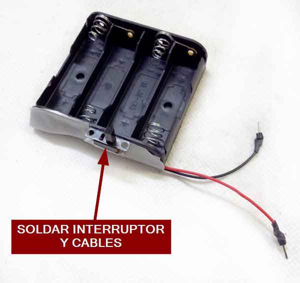
Next, add the switch to the battery holder. You will have to solder the cables to the switch you have, which can be like the one I show or any other.
In my case, I stick the switch to the battery holder itself, and cover/protect the cables with a piece of insulating tape. You can also put the switch on the chassis and run the cables there. I like to stick it on the battery holder itself, so it becomes a single compact module, easier to assemble.
Here it is important that you have a color criterion in the cables, using red cable for positive, and black cable for negative.
In the rest of the assembly, we will not need the soldering iron anymore.
We move on to the chassis. In my case, the base is made of acrylic, but, depending on the seller, it can also be black plastic, wood, or even sheet metal.
We add the caster wheel using the brass spacers, screws, and nuts.
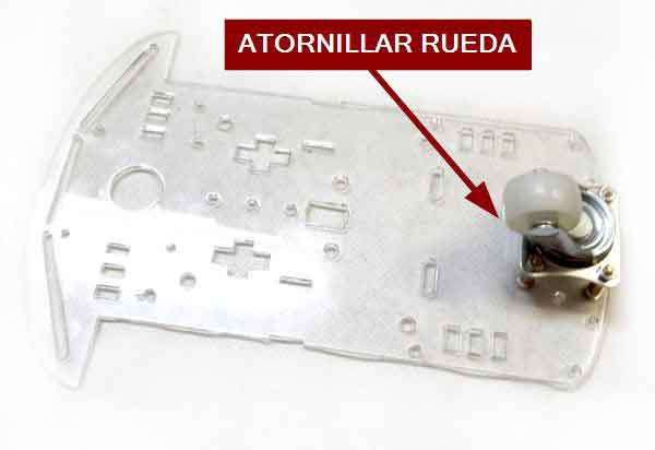
Those of you with plastic bases, especially acrylic, be careful when applying force to the base and when screwing because it is fragile and can break.
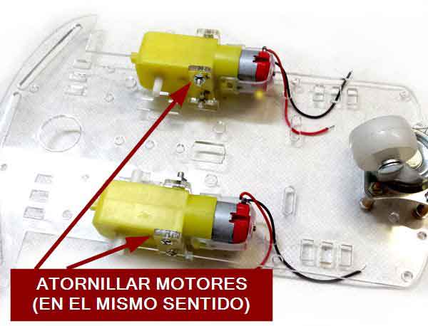
Next, screw the motors using the “T” pieces. We insert the pieces into the slots of the base, put the motor in the middle, and use screws to go from side to side and put a thread.
It is important that the motors are in the same direction. The tendency is to put them symmetrical (with the cables of both motors inwards or outwards) but it is better to put them in the same direction, because this way when the motor moves forward or backward, both motors rotate in the same direction.
The motors do not work exactly the same when rotating in one direction as in the other, and putting them in this way will make it easier for the motor to move straight later on.
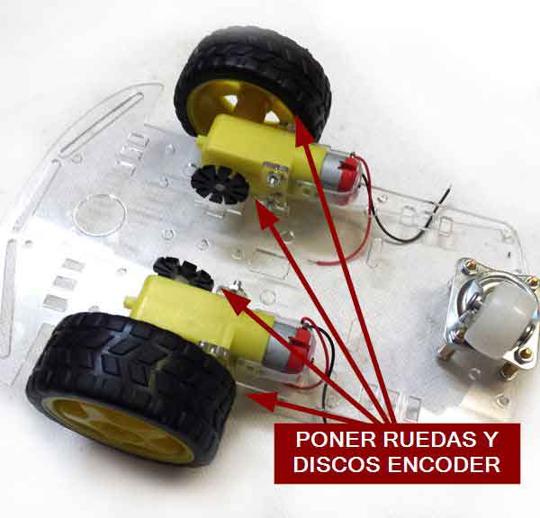
Now we attach the wheels and the slotted discs of the encoders on the shaft. We tighten carefully and make sure that no part touches anything (not even the end of the wheel with the body of the motor).
We turn the robot over, placing the wheels on the ground, pass the motor cables through the holes in the chassis and connect the power cables to the breadboard.
We also position the elements as seen in the following image. We have the battery holder, a mini breadboard with an Arduino Nano, and the L298N motor controller.
When we are comfortable with the arrangement and are sure that they do not interfere with each other or with the slots of the chassis, we proceed to fix them to the base.
The breadboard has its own adhesive, we just have to remove the protective paper and stick it to the base. For the battery holder, and the L29N, a couple of strips of double-sided tape on each one will be enough.
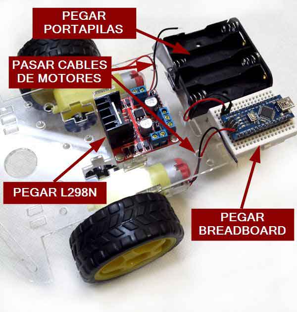
When attaching the components, hold the base from below with your hand to avoid applying force and breaking it.
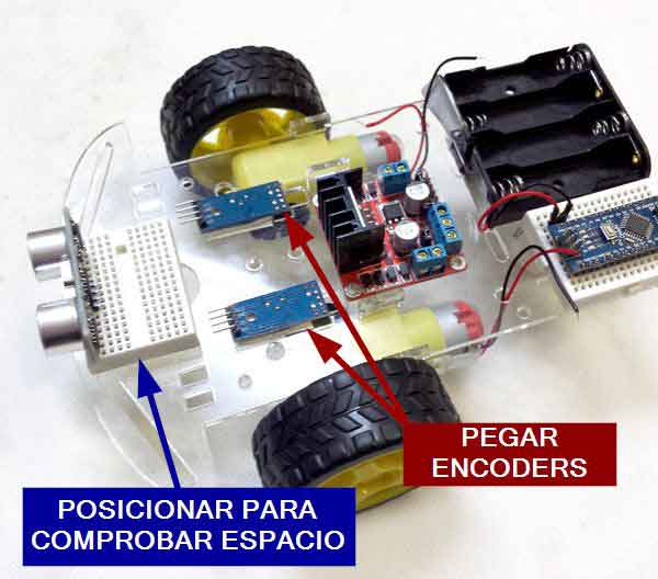
We move on to installing the encoders. We present the breadboard with the ultrasonic sensor to make sure that everything fits correctly.
We insert the “U” of the sensor into the chassis slot, leaving the slotted disk in the middle. If the disk rubs against the sensor, we can move it to ensure that it rotates correctly.
Finally, we fix the encoders to the base of the robot using a strip of double-sided tape on each sensor.
We connect the encoders and the L298N to the Arduino breadboard.
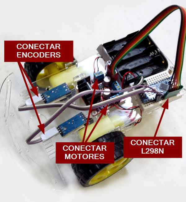
Do not worry about the connections now, as we will see them intensively in the next post.
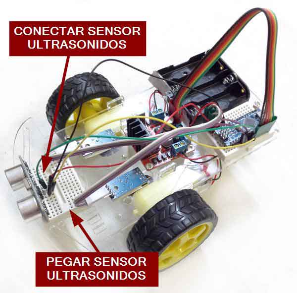
We put the ultrasonic sensor in place and stick it definitively with the breadboard adhesive, after removing the protective paper.
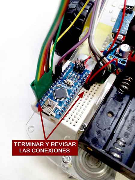
Finally, we finish making all the connections and review that everything is correct before adding the batteries.
The connections will be more or less as in the following image, although don’t worry about looking at the connections right now, because, as I said, we will see them in the next post (and I will probably change some cables to make it easier to assemble).
We have finished assembling our 2WD robot! If we wanted to mount a servo on the front HC-SR04 sensor, we would simply remove the front breadboard and put a servo.
If we want to add line detection sensors, we would stick them on the bottom of the sensor, getting them as close to the ground as possible, but keeping a distance of a few millimeters so that the robot does not “hit” any irregularity or bump in the terrain.
Similarly, if we want to use any other type of sensor, or motor controller, or processor, or if we want to add more sensors, or a Bluetooth module. It’s a matter of being inventive, positioning things well, and fixing them as best as possible.
But well, with a little glue, double-sided tape, and some plastic part that you recycle from something you are going to throw away, you will not have any problem to make different configurations and inventions. And that’s the most fun part!
That’s all for this post on the assembly of our first 2WD robot. In the next one, we will see the connection diagram (and some possible variations) and in the last one, some code examples.
Check out the rest of the articles in the Robot Car series.
Download the Code
All the code from this post is available for download on Github.