We continue with the series of posts aimed at making a cheap robot car. In the first post we saw the budget and in the second post the assembly of the robot. In this post, we will see the electrical connection scheme.
Throughout the series of posts, we have seen that there is not a single way to assemble our robot car, but one of the fun parts is that we can make different configurations to our liking. If you have any doubts about the possible variations, check the previous posts.
Among the many possible options and variations, we are going to see the electrical scheme that we are going to see is one of the most common,
- 4 AA battery holder
- Arduino Nano
- L298N motor controller
- Two infrared encoders
- HC-SR04 ultrasonic sensor mounted on a SG90 servo
- Infrared bar, for line follower.
This connection scheme is a general configuration that is useful to illustrate because it groups many different components (servo, ultrasonics, infrared). But insist that you can modify it to your liking as long as you have enough free pins.
General Scheme
We start with a general scheme of our robot, with the approximate arrangement of each device. In the next section, we will go into detail on each component.
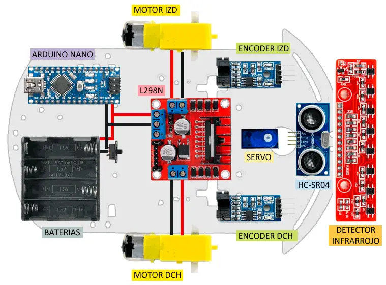
In broad strokes, the power is supplied by the battery holder that powers both the Arduino Nano and the L298N motor controller. We have a switch to turn the robot on or off. On the other hand, the L298N has both DC motors connected.
On the other hand, the Arduino Nano controls all the other devices. That is, Arduino controls the L298N, both encoders (left and right), the HC-SR04 ultrasonic sensor, the servo to move the HC-SR04, and the infrared bar for a line follower.
Detailed Schemes
Next, we will see the connection scheme of each component in detail. To make it easier to follow the connection, we have assigned a color to each component in the schemes. The following legend shows the color of each component in the schemes.
| Battery holder | |
|---|---|
| Arduino Nano | |
| L298N motor controller | |
| Encoders | |
| HC-SR04 ultrasonic sensor | |
| Servo | |
| Line detector |
Battery Holder
The robot’s power supply comes from the 4 AA battery holder, to which we put a switch in the negative to turn the robot on and off.
The connection is simple. We simply connect Gnd through the switch to the Gnd of the Arduino Nano and the L289N motor controller, and on the other hand, we power the Arduino Nano and the L298N by connecting Vcc, respectively, to Vin and Vm.
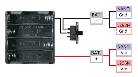
The 4 AA batteries give us a voltage between 5.8-6.4V, depending on the state of charge of the batteries. This is suitable for the motors we are mounting, so we power the L298N controller directly from the batteries.
On the other hand, this voltage is also suitable to turn on the Arduino Nano through the Raw port (or Vin) that uses the internal voltage regulator.
Do not power Arduino through the 5V pin, the voltage is too high and we can damage it.
Arduino Nano
The Arduino Nano is the brain of the entire system and controls all the other devices. It receives power from the batteries through the Raw (or Vin) pin, and Gnd.
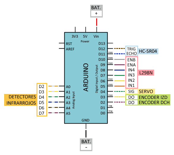
The Nano needs 6 pins to control the L298N, two of which must be PWM outputs. We also need 2 for the encoders, which should be associated with interruptions.
On the other hand, it controls the (optional) servo, HC-SR04 ultrasonic sensor, and the infrared detection bar.
L298N Motor Controller
The L298N motor controller receives power from the batteries through the Vm and GND pins. Since the voltage is 5.8-6.4V, the jumper on the board should be closed.
On the other hand, the L298N has the motors connected. The polarity determines the direction of rotation, but don’t worry because we can fix it later, even in the code.
What is convenient is that instead of connecting them “symmetrically” (which is the natural tendency), we connect them in the same position as you look at the plug. If not, a motor will rotate in the opposite direction (although we can also fix it later).
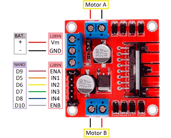
On the other hand, we have 6 control pins from Arduino. Of these, IN1, IN2, IN3, and IN4 control the direction of rotation, and ENA and ENB control the speed. These last two need to be PWM outputs.
For this reason, although it forces us to cross a cable, we have chosen that ENA and ENB are D9 and D10 because they are PWM outputs powered from the same Timer, which will favor the robot to go straight more easily.
If you need more information, check Controlling DC motors with Arduino and L298N.
Encoders
The connection of the encoders is very simple. We simply power both modules from Arduino through the Gnd and Vcc pins of the encoder. On the other hand, we connect the output pins (DO) of both modules to two digital pins of Arduino.
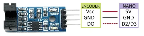
For the correct operation of the encoders, it is very convenient to use inputs associated with interruptions. In the case of Arduino Nano, remember that it has two pins with interruptions, D2 and D3.
If you need more information, check Optical encoder with a photointerrupter and Arduino.
HC-SR04 Ultrasonic Sensor
The connection of the HC-SR04 sensor is simple. We power it from Arduino through the 5V and Gnd pins of the HC-SR04.
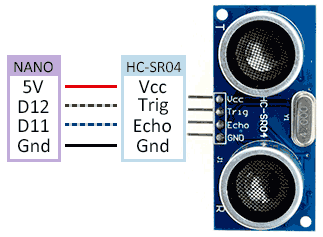
On the other hand, we connect Trig and Echo to two digital outputs of Arduino. Although, in the event of being short of pins, we could even control the HC-SR04 with a single pin.
If you need more information, check Measuring distance with HC-SR04 ultrasonic sensor.
Servo
Controlling a servo shouldn’t be a problem either. We power the module from Arduino by connecting Gnd and Vcc. On the other hand, we use any digital output for control.
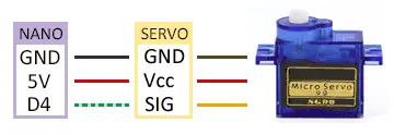
Being a small SG90 type servo Arduino can supply enough power to make it work by connecting it to its pins.
If you use a larger servo (like MG966R), for example to act on a claw, you will need a separate 5V source. With a supply voltage of 5.8-6.4V, in that case, we could connect our servo directly to the batteries.
If you need more information, check Controlling a servo with Arduino.
Line Detector
Finally, we have the infrared sensor bar to make a line follower. There are many types of bars, and we can even use individual infrared sensors.
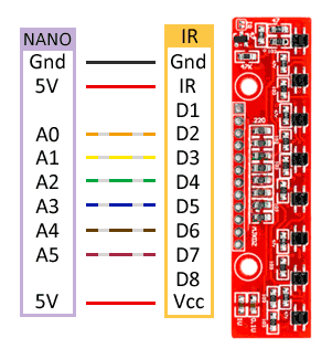
To make a line follower, the minimum number of sensors we will need is 2. The robot will try to keep the line between both, oscillating continuously.
With a greater number of sensors, the robot’s behavior improves a lot because, knowing how far we are from the line, we can improve control (for example, implementing a PID). A good number of sensors is 5, for example.
The bar in the scheme has 8 sensors, many more than we need, and we don’t want to use so many Arduino pins for this. So we only connect 6 of them.
The connection is simple, we power the module by connecting Gnd and 5V to the corresponding pins of Arduino. We also connect 5V to IR, to turn on the infrared LEDs. Finally, we connect the 6 central inputs to 6 analog inputs of Arduino, to read the sensor.
Conclusion
We already have everything we need to connect and finish assembling our robot! Beyond the particular scheme, the most interesting thing is that you see why each thing is connected where it is connected and the function of each component in the robot.
So you can play with the configuration of the robot. If you don’t want the infrared sensor bar, don’t add it for now! Do you want to put three fixed ultrasonic sensors, instead of one on top of the servo? Remove the servo. Prefer another distance sensor, add a laser, a claw… adjust the project to your needs.
In the next post in the series, we will start with the basic programming to move our robot, and in future posts, we will delve into the control of encoders, distance sensors, and line followers.
Check the rest of the articles in the Robot Car series.
If you liked this post and want to read more about Arduino, you can check the section ARDUINO TUTORIALS.
Download the code
All the code from this post is available for download on Github.