What is a Real Time Clock RTC?
A real-time clock (RTC) is an electronic device that allows us to obtain time measurements in the time units that we use on a daily basis.
The term RTC was created to differentiate this type of clock from the usual electronic clocks, which simply measure time by counting pulses of a signal, without a direct relationship with time units.
On the other hand, RTCs are more similar to the clocks and calendars that we usually use, and that operate with seconds, minutes, hours, days, weeks, months, and years.
RTC’s are usually made up of a crystal resonator integrated with the electronics necessary to correctly count the passage of time. The electronics of the RTC take into account the peculiarities of our way of measuring time, such as the sexagesimal system, months with different days, or leap years.
RTC’s provide the advantage of reducing energy consumption, providing greater precision, and freeing Arduino from having to perform time counting. In addition, RTCs frequently incorporate some type of battery that allows the time value to be maintained in case of power loss.
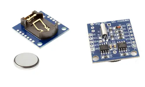
In the world of home electronics and Arduino, there are two common RTCs, the DS1307 and the DS3231, both manufactured by Maxim (formerly Dallas Semiconductor). The DS3231 has much higher precision and can be considered a replacement for the DS1307.
In the DS1307 model, temperature variations that affect the measurement of time by the resonator crystals result in errors in accumulated deviation. This causes the DS1307 to suffer from a time deviation, which can be 1 or 2 minutes per day.
To solve this, the DS3231 incorporates temperature measurement and compensation, guaranteeing a precision of at least 2ppm, which is equivalent to a maximum deviation of 172ms/day or one second every 6 days. In the real world, they usually achieve superior precisions, equivalent to deviations of 1-2 seconds per month.
Communication in both models is carried out through the I2C bus, making it easy to obtain the measured data. The supply voltage is 4.5 to 5.5 for the DS1307, and 2.3 to 5.5V for the DS3231.
These modules frequently also incorporate a small AT24C32 EEPROM, which can be used to store records and measurements. In the case of the DS3231, temperature measurement is also available, although it has low precision of ±3ºC, and the acquisition time can last up to 1 second.
They also incorporate a CR2032 battery to keep the device on time when the power is removed. This battery should be able to keep the DS1307 powered for several years, and the DS3231 powered for months. The battery supply voltage is 2.0 to 3.5 for the DS1307 and 2.3 to 5.0 for the DS3231.
RTC’s are widely used devices in electronics. All personal computers, servers, tablets, and smartphones incorporate one. They are also very common in embedded systems and, in general, in a multitude of devices that require time logging.
In our electronics projects, we frequently need an RTC. For example, we can time the turning on of lights or irrigation systems, create a datalogger, or even turn the Arduino on and off to save battery.
Price
RTC’s are very cheap devices. We can find the DS1307 for €0.50, searching in international sellers on eBay or AliExpress.
The DS3231, the replacement for the DS1307, is currently even cheaper. We can find it for €0.40.
Since the DS3231 is superior in features and has a lower price, it is logical to always prefer modules with DS3231 over DS1307.
Assembly diagram
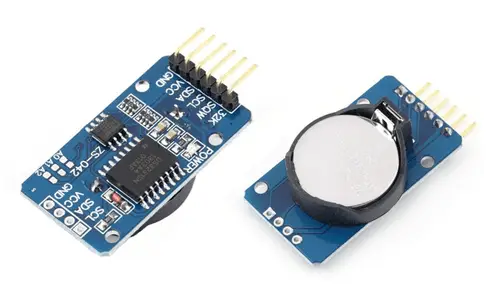
The connection is simple and similar for both the DS1307 and the DS3231. We simply power the module from Arduino using 5V and Gnd. On the other hand, we connect the I2C bus pins to the corresponding pins on Arduino.
The connection of a module with DS1307 would be as follows,
Similar to that of a module with DS3213, which would be as follows,
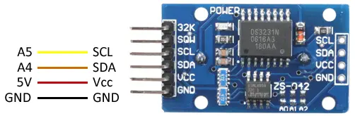
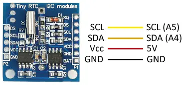
In both cases, the connection, seen from the Arduino side, is the same, and would look like this.
In Arduino Uno, Nano, and Mini Pro, SDA is pin A4 and SCK is pin A5. For other Arduino models, refer to the pinout scheme corresponding.
Code examples
To read the DS1307 and the DS3231, we will use the library developed by Adafruit, which is valid for both models, available at this link. The library provides code examples, which are advisable to review.
Get the date and time
The first example uses the RTC to obtain the current date and time data. Subsequently, these values are used to display them via the serial port. It also shows how to set the date and time, and detect power loss.
#include <Wire.h>
#include "RTClib.h"

// RTC_DS1307 rtc;
RTC_DS3231 rtc;

String daysOfTheWeek[7] = { "Sunday", "Monday", "Tuesday", "Wednesday", "Thursday", "Friday", "Saturday" };
String monthsNames[12] = { "January", "February", "March", "April", "May",  "June", "July","August","September","October","November","December" };

void setup() {
  Serial.begin(9600);
  delay(1000);

  if (!rtc.begin()) {
    Serial.println(F("Couldn't find RTC"));
    while (1);
  }

  // If power is lost, set the date and time
  if (rtc.lostPower()) {
    // Set to the compilation date and time
    rtc.adjust(DateTime(F(__DATE__), F(__TIME__)));

    // Set to a specific date and time. In the example, January 21, 2016 at 03:00:00
    // rtc.adjust(DateTime(2016, 1, 21, 3, 0, 0));
  }
}

void printDate(DateTime date)
{
  Serial.print(date.year(), DEC);
  Serial.print('/');
  Serial.print(date.month(), DEC);
  Serial.print('/');
  Serial.print(date.day(), DEC);
  Serial.print(" (");
  Serial.print(daysOfTheWeek[date.dayOfTheWeek()]);
  Serial.print(") ");
  Serial.print(date.hour(), DEC);
  Serial.print(':');
  Serial.print(date.minute(), DEC);
  Serial.print(':');
  Serial.print(date.second(), DEC);
  Serial.println();
}

void loop() {
  // Get the current date and display it via Serial
  DateTime now = rtc.now();
  printDate(now);

  delay(3000);
}
Scheduled on and off
The next example is a common project, using an RTC to turn a device on or off at specific times and dates. For example, it can be used to control garden irrigation, turn on lights, heating, deploy an awning, or control any other device using a relay.
The IsScheduledON function controls the on and off. In the example, it is programmed to turn on on Wednesdays, Saturdays, and Sundays from 09:30 to 11:30 and from 21:00 to 23:00. By modifying the body of this function, you can program the on and off condition you need.
#include <Wire.h>
#include "RTClib.h"

const int outputPin = LED_BUILTIN;
bool state = false;

// RTC_DS1307 rtc;
RTC_DS3231 rtc;

void setup() {
  Serial.begin(9600);
  delay(1000);

  if (!rtc.begin()) {
    Serial.println(F("Couldn't find RTC"));
    while (1);
  }

  if (rtc.lostPower()) {
    rtc.adjust(DateTime(F(__DATE__), F(__TIME__)));
  }
}

// Check if the device is scheduled to be turned on
bool isScheduledON(DateTime date)
{
  int weekDay = date.dayOfTheWeek();
  float hours = date.hour() + date.minute() / 60.0;

  // From 09:30 to 11:30 and from 21:00 to 23:00
  bool hourCondition = (hours > 9.50 && hours < 11.50) || (hours > 21.00 && hours < 23.00);

  // Wednesday, Saturday, or Sunday
  bool dayCondition = (weekDay == 3 || weekDay == 6 || weekDay == 0);
  if (hourCondition && dayCondition)
  {
    return true;
  }
  return false;
}

void loop() {
  DateTime now = rtc.now();

  if (state == false && isScheduledON(now))    // Off and should be on
  {
    digitalWrite(outputPin, HIGH);
    state = true;
    Serial.print("Activated");
  }
  else if (state == true && !isScheduledON(now))  // On and should be off
  {
    digitalWrite(outputPin, LOW);
    state = false;
    Serial.print("Deactivate");
  }

  delay(3000);
}
Datalogger with RTC
The following example shows another very common case, the use of an RTC to generate a datalogger, that is, a device that periodically records the measurement of a sensor. In the example, we will use an SD card to save the values.
Simply, we obtain the date, time, and sensor value, which in the example we simulate with the readSensor() function, and save the data on the card with the logValue(,,) function.
In a real project, we could save one or more measurements, separated by commas, for example. We could also vary the time of measurement, which in the example is done every 10 seconds, to, for example, when an event occurs, or at certain times of the day using the RTC itself.
#include <SPI.h>
#include <SD.h>
#include <Wire.h>
#include "RTClib.h"

File logFile;

// RTC_DS1307 rtc;
RTC_DS3231 rtc;

void setup()
{
  Serial.begin(9600);
  Serial.print(F("Initializing SD ..."));
  if (!SD.begin(4))
  {
    Serial.println(F("Error initializing"));
    return;
  }
  Serial.println(F("Initialized correctly"));
}

// Function that simulates reading a sensor
int readSensor()
{
  return 0;
}

void logValue(DateTime date, int value)
{
  logFile.print(date.year(), DEC);
  logFile.print('/');
  logFile.print(date.month(), DEC);
  logFile.print('/');
  logFile.print(date.day(), DEC);
  logFile.print(" ");
  logFile.print(date.hour(), DEC);
  logFile.print(':');
  logFile.print(date.minute(), DEC);
  logFile.print(':');
  logFile.print(date.second(), DEC);
  logFile.print(" ");
  logFile.println(value);
}

void loop()
{
  // Open file and write value
  logFile = SD.open("datalog.txt", FILE_WRITE);

  if (logFile) {
    int value = readSensor();
    DateTime now = rtc.now();

    logValue(now, value);
    logFile.close();

  }
  else {
    Serial.println(F("Error opening the file"));
  }
  delay(10000);
}
Download the code
All the code in this post is available for download on Github. 
