In this post, we are going to see how to connect, send, and receive data between two processors like Arduino using the I2C communication bus.
The I2C bus is one of the best alternatives for connecting devices together. As we have seen in many posts, a large number of devices use I2C to communicate with Arduino.
If you are not yet familiar with the I2C bus, we recommend you check out the basic post about the I2C bus.
But the I2C bus is not only useful for communicating with all kinds of sensors; we can also use it to connect two or more microprocessors using just two wires for communication.
What could this be useful for? Many things. The most typical is connecting different microprocessors, for example, combining an ESP8266/ESP32 + Arduino, or Raspberry Pi + Arduino in a project.
It could also be that in a project we need more pins than we have available, although we could consider alternatives like using multiplexers or a different board like a Mega.
Another possible use is in the case of a machine that has multiple groups of sensors, and it is preferable to use several local microprocessors and coordinate them with each other.
Finally, it is also useful when we are short on computing power. For example, in the case of one or several subsystems that require high-frequency monitoring and periodically pass the data to a hierarchically superior processor.
In any case, connecting microprocessors via the I2C bus is a very interesting and useful option. Potentially, we could set up a network of up to 127 processors! So, let’s get to it!
Connection Diagram
The connection is actually very simple. We simply power the supply (5V and GND) of both Arduinos, and connect the two I2C pins (SDA, SCL) from each Arduino to the SDA and SCL pins of the other.
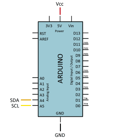
If powering both Arduinos via micro USB, disconnect Vcc between them and leave only GND as a common voltage reference.
On the other hand, if any of the devices operates at different voltages (for example, 5V and 3.3V), you will need to place a level shifter adapter in between, as we saw in this post.
Keep in mind that the I2C bus is designed to work over short distances, typically a maximum of 20-30 cm. However, there are I2C bus extenders that use twisted-pair cables (similar to UART over RS485) that can achieve over 300 m.
Finally, the I2C bus needs pull-up resistors. Arduinos have internal resistors, but they are weak (high value). If you have communication problems, try reducing the cable length or adding external 4K7 resistors.
Code Example
Master Code
As for the code, it is also quite simple. In the I2C bus, one of the devices acts as the Master and can send information to the Followers.
Followers cannot initiate communication with the Master (that’s why they are called Followers), but the Master can request information from a Follower and the Follower can send it.
As an example, we will simply send and receive a ‘long’ variable, which in Arduino has a length of 4 bytes and is a good example for sending variables larger than one byte.
#include "Wire.h"

const byte I2C_FOLLOWER_ADDR = 0x20;

long data = 100;
long response = 0;

void setup()
{
  Serial.begin(115200);
  Wire.begin();
}

void loop()
{
  sendToFollower();
  requestToFollower();
  delay(2000);
}

void sendToFollower()
{
  Wire.beginTransmission(I2C_FOLLOWER_ADDR);
  Wire.write((byte*)&data, sizeof(data));
  Wire.endTransmission();
}

void requestToFollower()
{
  response = 0;
  Wire.requestFrom(I2C_FOLLOWER_ADDR, sizeof(response));

  uint8_t index = 0;
  byte* pointer = (byte*)&response;
  while (Wire.available())
  {
    *(pointer + index) = (byte)Wire.read();
    index++;
  }

  Serial.println(response);
}
Using the same example, we could display a structure containing a grouping of several variables as a message.
Let’s look at the Master code that shows both cases. First, the Master initiates I2C communication with ‘Wire.begin()’, without any address as a parameter. This indicates that the Arduino will act as the master.
As we can see, the ‘sendToFollower’ function is very simple. We simply start communication with one of the Followers and transmit the bytes of the message (in our case, a ‘long’ variable).
The ‘requestToFollower’ function is not much more difficult. We request a number of bytes from one of the Followers and receive them in the following loop.
Follower Code
On the other hand, the Follower code would be as follows. The Follower initiates the I2C bus with ‘begin(…ADDRESS…)’, indicating that this Arduino will function as a Follower at the address passed as a parameter.
#include "Wire.h"

const byte I2C_FOLLOWER_ADDR = 0x20;

void setup()
{
  Serial.begin(115200);

  Wire.begin(I2C_FOLLOWER_ADDR);
  Wire.onReceive(receiveEvent);
  Wire.onRequest(requestEvent);
}

long data = 0;
long response = 200;

void receiveEvent(int bytes)
{
  data = 0;
  uint8_t index = 0;
  while (Wire.available())
  {
    byte* pointer = (byte*)&data;
    *(pointer + index) = (byte)Wire.read();
    index++;
  }
}

void requestEvent()
{
  Wire.write((byte*)&response, sizeof(response));
}

void loop() {

  if (data != 0)
  {
    Serial.println(data);
    data = 0;
  }
}
Next, we associate the callback functions to the events ‘Wire.onReceive(…)’ and ‘Wire.onRequest(…)’.
In the function associated with the ‘onReceive’ event, we collect the data sent from the master and store it in the variable ‘data’. In the main loop, we check if the value of ‘data’ has changed and, if so, we display it via the serial port.
On the other hand, the function associated with ‘onRequest’ simply returns the variable ‘response’.
In a real project, of course, this data would not be fixed values, and we would do something with them afterwards. But for the example, it is sufficient.
Conclusion
As we can see, it is quite simple to connect two or more processors like Arduino via the I2C bus. In general, it is useful in advanced projects whose complexity justifies the additional difficulty of using more than one microprocessor.
The main limitation is that both Arduinos have to know and share exactly the type of message they are going to receive. Typically, we will define a structure containing the data we want to exchange.
Another limitation is that sending data via I2C in Arduino is limited to 32 bytes in the ‘Wire.h’ library. It can be extended up to a maximum of 64 bytes, but in certain projects, this may be insufficient.
So, for example, if you were thinking of using it to receive information encoded in Json format from an ESP8266, I’m sorry to say you will have difficulties.
But don’t worry! Precisely in the next post, we will see how to avoid these limitations to receive communication of arbitrary and unknown length. See you soon!
