What is the PCA9685?
The PCA9685 is an I2C-controlled PWM controller that we can connect to a processor like Arduino to increase the number of available PWM outputs in a simple way.
The PCA9685 was originally designed to generate PWM signals, mainly for LED control. However, since servos use a PWM signal, it is also common to use the PCA9685 as a servo controller.
The PCA9685 allows for up to 16 PWM signals to be generated, or to control 16 servos, using only 2 pins. The PWM frequency is adjustable up to 1600 Hz, with a precision of 12 bits.
Communication is done through the I2C bus, making it easy to obtain the measured data. It has 6 address pins, which means that up to 62 modules can be addressed. Up to 62 modules can be connected to generate a total of 992 PWM outputs.
All outputs are configurable as either push-pull or open-drain. It also has an output enable pin, which allows all outputs to be quickly deactivated simultaneously.
The PCA9685 has its own clock and the necessary electronics to generate the PWM signals, meaning it is not necessary to constantly send the signal from Arduino, which is then free to perform other processes.
Price
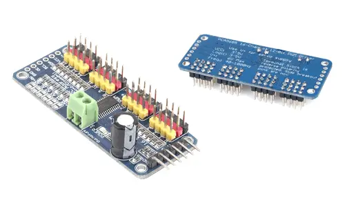
We can find a 16-channel PWM signal generator/servo controller module based on the PCA9685 for €1.40, by searching international sellers on eBay or AliExpress.
Assembly diagram
The connection is simple, we simply power the module from Arduino using GND and 5V, and connect the SDA and SCL pins of Arduino with the corresponding pins on the sensor.
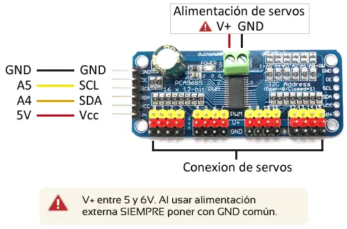
While the connection seen from the Arduino side would look like this.
For the connection of the servos, we have 16 columns of 3 pins. The power supply for the servos is provided from a separate power source, as they require a higher current than a processor can deliver. For this, there is a connection terminal with protection against reverse polarity.
On Arduino Uno, Nano, and Mini Pro, SDA is pin A4 and SCK is pin A5. For other Arduino models, check the pinout diagram accordingly.
When using multiple power sources, always put a common voltage Gnd reference.
Code examples
To read the PCA9685, we will use the library developed by Adafruit, available at this link.
The library provides code examples, which it is advisable to review. The following examples are modifications based on those available in the library.
PWM output generator
The following code shows the use of the PCA9685 as a PWM output generator. In it, we generate a 1600 Hz PWM output on all channels, and adjust the duty from 0% to 100%.
The PWM is configured by marking the on and off times in a number of ticks from 0 to 4095. The width of a tick in milliseconds will depend on the chosen frequency.
//SCL -> A5
//SDA -> A4

#include <Wire.h>
#include <Adafruit_PWMServoDriver.h>

Adafruit_PWMServoDriver pwm = Adafruit_PWMServoDriver(0x40);

void setup()
{
  pwm.begin();

  // Set the frequency to the maximum (1600Hz)
  pwm.setPWMFreq(1600);
}

void loop()
{
  for (uint16_t duty = 0; duty < 4096; duty += 8)
  {
    for (uint8_t pwmNum = 0; pwmNum < 16; pwmNum++)
    {
      // Adjust PWM with ON at tick=0 and OFF at tick=duty
      pwm.setPWM(pwmNum, 0, duty);
    }
  }
}
Servo controller
The following example shows the use of the PCA9685 as a servo controller. The example uses 50 Hz servos. It is necessary to set the number of ticks equivalent to 0° and 180°.
//SCL -> A5
//SDA -> A4

#include <Wire.h>
#include <Adafruit_PWMServoDriver.h>

Adafruit_PWMServoDriver servoController = Adafruit_PWMServoDriver(0x40);

const uint8_t frequency = 50;    // 50Hz PWM frequency or T=20ms
const uint16_t ServoMinTicks = 102; // pulse width in ticks for 0° position
const uint16_t ServoMaxTicks = 512; // pulse width in ticks for the 180° position

void setup()
{
  servoController.begin();
  servoController.setPWMFreq(frequency );
}

void loop()
{
  for (uint16_t duty = ServoMinTicks; duty < ServoMaxTicks; duty++)
  {
    for (uint8_t n = 0; n<16; n++)
    {
      servoController.setPWM(n, 0, duty);
    }
  }
  delay(1000);

  for (uint16_t duty = ServoMaxTicks; duty > ServoMinTicks; duty++)
  {
    for (uint8_t n = 0; n<16; n++)
    {
      servoController.setPWM(n, 0, duty);
    }
  }
  delay(1000);
}
If we want to work with ms instead of ticks, we will need a function that performs the conversion. However, whenever possible, the previous code in ticks is preferable because it allows for greater precision.
//SCL -> A5
//SDA -> A4

#include <Wire.h>
#include <Adafruit_PWMServoDriver.h>

Adafruit_PWMServoDriver servoController = Adafruit_PWMServoDriver(0x40);

const uint8_t frequency = 50;    // 50Hz PWM frequency or T=20ms
const uint16_t ServoMinMs = 500;  // Pulse width in ms for 0° position
const uint16_t ServoMaxMs = 2500; // Pulse width in ms for the 180° position

void setup()
{
  servoController.begin();
  servoController.setPWMFreq(frequency);
}

void setServoPulse(uint8_t n, double pulseMs)
{
  double bitlength;
  // 1,000,000 us per second / frequency / 4096 (12 bits)
  bitlength = 1000000 / frequency / 4096;
  double duty = pulseMs / bitlength;
  servoController.setPWM(n, 0, pulseMs);
}

void loop()
{
  for (uint16_t pulseWidth = ServoMinMs; pulseWidth < ServoMaxMs; pulseWidth = pulseWidth + 10)
  {
    for (uint8_t n = 0; n<16; n++)
    {
      setServoPulse(n, pulseWidth);
    }
  }
  delay(1000);

  for (uint16_t pulseWidth = ServoMaxMs; pulseWidth > ServoMinMs; pulseWidth = pulseWidth - 10)
  {
    for (uint8_t n = 0; n<16; n++)
    {
      setServoPulse(n, pulseWidth);
    }
  }
  delay(1000);
}
Download the code
All the code from this post is available for download on Github. 
