One of the best ways we have to control a robot remotely is to use a Playstation 2 controller. On the Internet you can find many examples that choose this controller for its exceptional technical characteristics, even in professional projects. Furthermore, it is really cheap, something especially important in our home projects.
Among its characteristics as a controller the PS2 controller is wireless and has a fairly acceptable range. On the other hand, it has a wide variety of inputs that include 4 pressure-sensitive directional buttons, 4 pressure-sensitive action buttons, 2 analog sticks, and 4 digital buttons located on the front.
As for the price, a clone of this controller can be obtained on Ebay for 9.90€. An incredible price that, together with its technical characteristics, make it one of the best options to control a robot at a minimal cost.
In this tutorial we are going to learn how to connect the PS2 controller to Arduino to be able to use it in our projects and control robots and automations wirelessly.
Necessary material
In addition to our Arduino (mini, Uno, Mega, or the one you prefer), the first thing we need is, logically, a wireless PS2 controller. A simple search on Ebay will show us a large number of clones. We are looking for one in the range of 9 to 10€, cheap but with a minimum of quality.
On the other hand, in most cases we will need a 3.3V to 5V level converter. The reason is that, generally, our Arduino operates at 5V, while the electronics of the PS2 controller operates at 3.3V. We could make our own adaptation circuit, but it doesn’t make any sense since they are sold for 1.10€, shipping included.
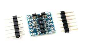
To find the converter simply search for “level converter” on Ebay. We are looking for an item similar to the following “JY MCY I2C LEVEL CONVERTER”, a device that allows to adapt 4 signals bidirectionally. Note that the model we want has 6 pins (do not buy one with 4 pins, which can only adapt 2 signals).
Connection and assembly
The entire assembly is carried out exclusively on the receiver, so we can leave the controller itself “quiet”. First, we remove the screws from the receiver to access the terminals. We unsolder the connection pins and replace them with our own cables, which we will solder to the receiver board. We close the receiver, leaving the cables coming out where the connection with the video console was before.
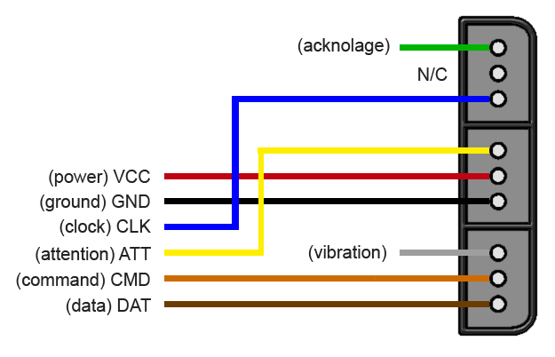
Now we use a multimeter to identify the function of each of the cables we have soldered. Do not trust the Internet schematics, which identify each terminal by the color of the cable they had soldered, because the color of the cables and their connection vary from one manufacturer to another. Verify it manually with a multimeter and the help of the following diagram.
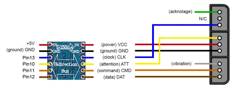
Next, we use a protoboard to make the connections with our digital converter (or solder it directly). On the low voltage side, we connect the four controller signals, ground, and power supply, which will be provided by Arduino. On the high voltage side, we connect four pins, ground, and +5V, which will be converted by the converter to +3.3V to power the receiver.
The final scheme is as follows.
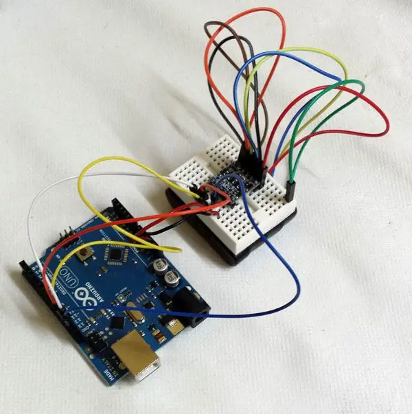
Here you can see an example of the final assembly, connected to an Arduino Uno.
And here a similar assembly connected to an Arduino Mini.
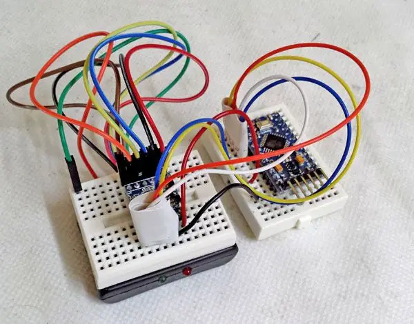
With this combination we have a fairly compact assembly that easily fits in any robot, and with the free pins of both protoboards we have enough connections for the rest of the elements that require it.
Library and code
Let’s go for the code. Fortunately for us, the difficult part is resolved in a magnificent library available at https://github.com/madsci1016/Arduino-PS2X. Simply download and import the library, and load the example Sketch.
The example code is too extensive and has too many lines (as it is logical since the goal is to show all the possibilities). It is not difficult at all to analyze and adapt it to our needs. However, I leave a reduced code so that you can easily use it as a starting point for your projects.
#include <PS2X_lib.h>

PS2X ps2x;

int error = 0;
byte type = 0;
byte vibrate = 0;

void setup(){
  Serial.begin(57600);

  error = ps2x.config_gamepad(13,11,10,12, true, true);   //setup pins and settings:  GamePad(clock, command, attention, data, Pressures?, Rumble?) check for error

  if(error == 0){
    Serial.println("Found Controller, configured successful");
    Serial.println("Try out all the buttons, X will vibrate the controller, faster as you press harder;");
    Serial.println("holding L1 or R1 will print out the analog stick values.");
    Serial.println("Go to www.billporter.info for updates and to report bugs.");
  }

  else if(error == 1)
  Serial.println("No controller found, check wiring, see readme.txt to enable debug. visit www.billporter.info for troubleshooting tips");

  else if(error == 2)
  Serial.println("Controller found but not accepting commands. see readme.txt to enable debug. Visit www.billporter.info for troubleshooting tips");

  else if(error == 3)
  Serial.println("Controller refusing to enter Pressures mode, may not support it. ");

  type = ps2x.readType();
}

void loop(){

  if(type == 1){
    ps2x.read_gamepad(false, vibrate);  //Read the status

    //Read the directional buttons
    if(ps2x.Button(PSB_PAD_UP)) {
      Serial.print("Up held this hard: ");
      Serial.println(ps2x.Analog(PSAB_PAD_UP), DEC);
    }
    if(ps2x.Button(PSB_PAD_RIGHT)){
      Serial.print("Right held this hard: ");
      Serial.println(ps2x.Analog(PSAB_PAD_RIGHT), DEC);
    }
    if(ps2x.Button(PSB_PAD_LEFT)){
      Serial.print("LEFT held this hard: ");
      Serial.println(ps2x.Analog(PSAB_PAD_LEFT), DEC);
    }
    if(ps2x.Button(PSB_PAD_DOWN)){
      Serial.print("DOWN held this hard: ");
      Serial.println(ps2x.Analog(PSAB_PAD_DOWN), DEC);
    }

    //Read the button status
    if (ps2x.NewButtonState())
    {
      if(ps2x.Button(PSB_RED))
      Serial.println("Circle pressed");
      if(ps2x.Button(PSB_GREEN))
      Serial.println("Triangle pressed");
      if(ps2x.Button(PSB_PINK))
      Serial.println("Square pressed");
      if(ps2x.Button(PSB_BLUE))
      Serial.println("X pressed");

      if(ps2x.Button(PSB_START))
      Serial.println("Start is being held");
      if(ps2x.Button(PSB_SELECT))
      Serial.println("Select is being held");

      if(ps2x.Button(PSB_L3))
      Serial.println("L3 pressed");
      if(ps2x.Button(PSB_R3))
      Serial.println("R3 pressed");
      if(ps2x.Button(PSB_L2))
      Serial.println("L2 pressed");
      if(ps2x.Button(PSB_R2))
      Serial.println("R2 pressed");
    }

    //Read the analog sticks
    Serial.print("StickValues:");
    Serial.print(ps2x.Analog(PSS_LY), DEC); //Left controller
    Serial.print(",");
    Serial.print(ps2x.Analog(PSS_LX), DEC);
    Serial.print(",");
    Serial.print(ps2x.Analog(PSS_RY), DEC); //Right controller
    Serial.print(",");
    Serial.println(ps2x.Analog(PSS_RX), DEC);
  }
  else
  {
    return;
  }

  delay(500);
}Finally, in general, the library itself is quite heavy and consumes a good part of the memory of our small Arduino. However, it is possible to optimize and reduce it by removing code parts dedicated to other controllers (guitar hero, for example). It is also a good learning exercise, so I invite you to read it and try to optimize it.
Download the code
All the code in this post is available for download on Github.

