What is a fan?
A fan is a hydraulic machine that increases the kinetic energy of a gas, usually air. Fans are common objects in our daily lives and, like many other devices, we can control them from a processor like Arduino.
A fan has a rotor with blades (or vanes) driven, usually, by an electric motor. When rotating, the blades propel the air molecules, increasing their kinetic energy with little change in volume, which is why they are considered hydraulic machines instead of turbo machines.
In the field of home electronics, it is common to use fans like those used in computers for heat dissipation in computers. These fans are available in a wide variety of sizes, with 40x40mm, 80x80mm, and 120x120mm being common. The supply voltage is normally 12V.
Industrially, fans are used in all types of applications, such as temperature control, air conditioning installations, gas homogenization, smoke evacuation, machinery cooling, or heat dissipation in refrigeration systems.
In our home electronics projects, we can use fans, for example, to control the temperature of a device in combination with a temperature sensor, to cool along with a Peltier plate or to evacuate gases in combination with a gas sensor.
Price
There are fans in a wide price range depending on their technical characteristics, mainly the flow they provide, which in turn depends on their power, speed, and size. These factors influence the noise level produced.
Within the domestic field, for example, we can find computer-type fans of 40x40mm for €1, 80x80mm for €1.5, and 120x120mm for €2.5, searching on international sellers on eBay and AliExpress.

Assembly diagram
The assembly diagram is simple, we are simply going to use a MOSFET like the IRF520N as a switch to control the fan’s on/off.
On the one hand, we power the module with the nominal voltage of the fan, through GND and Vin.
On the other hand, we connect the load through the connection terminal. A fan, unless it is internally balanced, is an inductive load. Therefore, we must add a flyback protection diode, as we saw in the MOSFET entry.
Finally, we power the module’s electronics by connecting Vcc and GND to 5V and GND on Arduino, and connect Pin SIG to any of the digital outputs of Arduino.
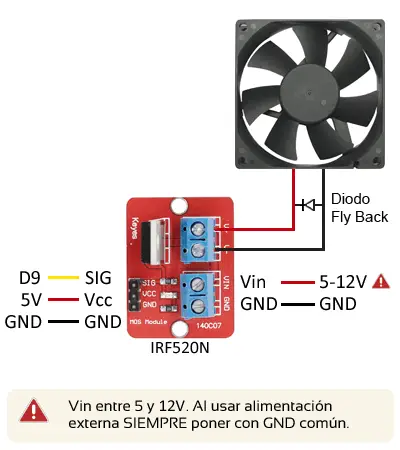
The connection, seen from Arduino, would be as follows.
We must take into account the supply voltage and the nominal current of the fan. If it consumes more than 1A, we must add a heat sink to the IRF520N, or use another model of MOSFET or even a relay output.
Code example
The necessary code is simple, since to control the fan we only need to use a digital output, as we saw in the digital outputs entry.
For example, the following code would simply turn the electromagnet on and off every 10 seconds.
const int pin = 9;

void setup() {
  pinMode(pin, OUTPUT);  //define pin as output
}

void loop(){
  digitalWrite(pin, HIGH);   // set the Pin to HIGH
  delay(10000);               // wait 10 seconds
  digitalWrite(pin, LOW);    // set the Pin to LOW
  delay(10000);               // wait 10 seconds

}
We can combine it with one of the many temperature sensors we have seen (thermistor, LM35, DS18B20, DHT11/DHT22) to turn on the fan according to the sensor’s measurement, maintaining a constant temperature.
Let’s assume that we have a certain function GetTemperature() that provides us with the sensor measurement. We must replace this function with the appropriate calculation, depending on the sensor we are using.
Now we define a certain hysteresis using two thresholds. When the temperature exceeds the upper threshold, it will trigger the fan to turn on. This will remain on until it reaches a lower threshold, and finally it will turn off when it reaches it.
If we defined a single threshold for activation and deactivation, we would have multiple turn-ons and turn-offs, and the sensor would be very sensitive to noise. In the end, we would end up damaging the relay.
const int pin = 9;

const float thresholdLOW = 20.0;
const float thresholdHIGH= 30.0;

bool state = false; /// active or inactive fan

float GetTemperature()
{
  return 20.0;  //replace as per the sensor used
}

void setup() {
  pinMode(pin, OUTPUT);  //define pin as output
}

void loop(){
  float currentTemperature = GetTemperature();

  if(state == false && currentTemperature > thresholdHIGH)
  {
      state = true;
      digitalWrite(pin, HIGH);   // turn on fan
  }
  if(state == true && currentTemperature < thresholdLOW)
  {
      state = false;
      digitalWrite(pin, LOW);   // turn off fan
  }

   delay(5000);  // wait 5 seconds between measurements
 }
Download the code
All the code from this post is available for download on Github. 
