What is a PCF8575?
The PCF8575 is a 16-bit I/O extender controlled by the I2C bus. This device allows us to have 16 additional GPIO using only two pins of a processor like Arduino.
The address of the PCF8575 is configurable through pins. In this way, we can include up to 8 of these devices on the same I2C bus, for a total of 128 additional GPIO.
The operating voltage is 2.5 to 5.5Vdc. The standby power consumption is about 10uA, and the maximum current it can provide is about 100mA.
Control is done by I2C up to 400kHZ, so it is very easy to control it from a microprocessor like Arduino.
The switching time is about 4us. However, although it is possible to use it to generate low-frequency square signals, it is not a suitable integrated circuit for generating high-frequency PWM signals.
To obtain PWM signals controllable by I2C, read the article about the PAC9685
Price
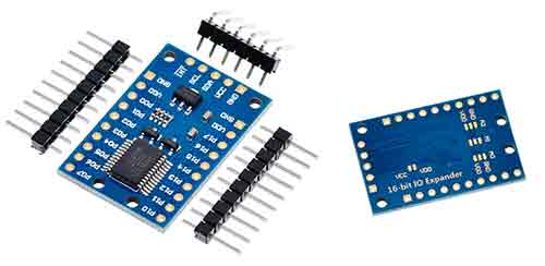
PCF8575 devices are relatively cheap. We can find a module with a PCF8575, including the measurement board, for 1.80€ from international sellers on eBay and AliExpress.
As we said, it is a relatively cheap device. It is cheap, but for a similar price range, we can find some processors. This would give us the same GPIO extension capability, as well as additional functionalities (PWM, analog readings, etc). In return, we would have higher complexity and higher energy consumption. You will have to evaluate the most appropriate solution for your project.
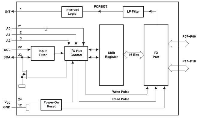
How does a PCF8575 work?
The PCF8575 is composed of 16 quasi-bidirectional GPIO, organized into two ports (P0-P07 and P10-P17). Each of the GPIO can be configured as an input or output.
Acting as outputs, each of them has a latch circuit. In other words, it is capable of maintaining the state by itself, without needing to be provided with an external voltage.
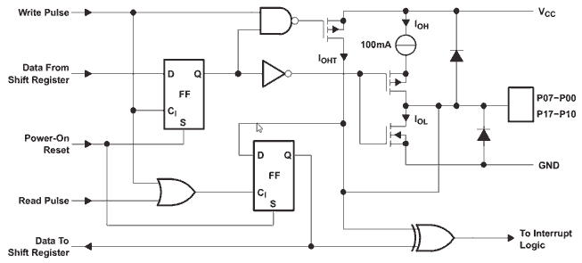
On the other hand, for a pin to be changed as an input, it is necessary to set a HIGH value beforehand. During startup, by default, all pins are initialized as inputs with a HIGH value.
Additionally, the PCF8575 provides an Open Drain configuration output pin, which can be used to inform the processor of a state change in one of the inputs, without having to constantly ask for the state by I2C.
Assembly diagram
The module is controlled via I2C, so the wiring is very simple. We simply power the module using Gnd and Vdd, and connect the I2C SDA and SCL pins.
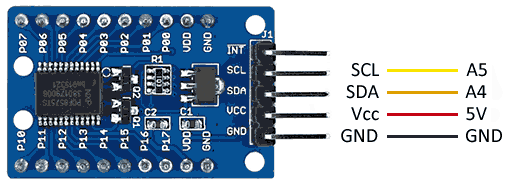
The connection seen from Arduino would be as follows.
Normally, in these modules, we can configure the I2C address of the PCF8575 by soldering some pins on the back of the module.
On the other hand, in some modules, the voltage of the GPIO outputs is fixed by an internal 3V3 regulator. To make the outputs work at 5V, we must power the module at 5V and, additionally, solder a pin on the back identified as Vdd-Vcc.
Code examples
To control the PCF8575, we can use the library developed by Xreef, whose code is available at https://github.com/xreef/PCF8575_library.
With this library, the use of the additional GPIO is very similar to what we would do with any other digital pin of the processor. By default, the library works in a range from P0 to P15, instead of P0 to P07 and P10 to P17.
The library includes examples of its use, which is advisable to consult. The following is a summary extracted from them.
#include "PCF8575.h"

// Initialize the PCF8575 at address 0x20
PCF8575 pcf8575(0x20);

void setup()
{
  Serial.begin(115200);

  // Set pin P0 as an output
  pcf8575.pinMode(P0, OUTPUT);

  pcf8575.begin();
}

void loop()
{
  pcf8575.digitalWrite(P0, HIGH);
  delay(1000);
  pcf8575.digitalWrite(P0, LOW);
  delay(1000);
}
Download the code
All the code from this post is available for download on Github. 
