We continue with the posts aimed at turning us into 3D experts within the 3D printing section. In the previous post, we saw the different types of 3D object representations. In this post, we will look at the conversion processes between them.
As with the previous post, we warn you that if what you’re looking for is to print as soon as possible, this post might offer you little or almost nothing. But we had already agreed that you are not looking to just print, but to become true 3D “masters” who get the most out of their 3D printer.
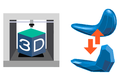
Understanding conversions is especially important in 3D printing (and even more so in 3D scanning) because, as we saw in the overview of the 3D printing process, we will be working with solids (CAD files) and meshes (STL files).
This is even more true as the trend in 3D software, like Fusion360, allows working simultaneously with solids, surfaces, and meshes.
This way we will avoid hearing “can you tell me the diameter of that 3D scanned part”, being surprised that we can’t edit an STL file with our CAD software (easily), or that our perfectly round hole is a polygon with straight sides when we 3D print it.
But before we start looking at the transformation processes, let’s put everything into perspective by seeing a little bit (a little bit, I promise) of theory.
Overview
In summary, we have two ways to represent geometry on a computer: continuous and discrete representations. The continuous form uses equations and mathematical models, while the discretized form contains information only at certain points in space.
Actually, these two modes, continuous and discrete, accompany us in many more situations than just representing geometry.
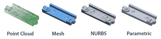
Classifying the ways to represent 3D objects we saw in the previous post, in summary, we have:
- Discrete: Point clouds and meshes (including triangulated, quads, and subdivision).
- Continuous: Surfaces and solids.
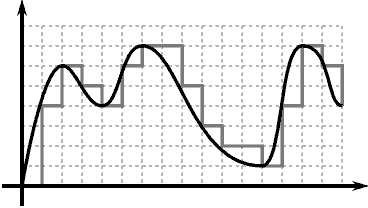
In principle, going from a continuous model to a discrete model is relatively straightforward by applying one of several possible algorithms. This sampling process basically takes the values of the continuous model at certain points, discarding the rest of the information.
The narrower the sampling interval, the closer the discrete model will be to the continuous one. But, in return, we will have a larger number of points, which means a larger file size and greater processing load.
Conversely, going from a discrete model to a continuous one is not trivial, being an exercise in interpolation. We are trying to “fit” a mathematical model to a discrete model, in which we have lost data during sampling.
If you have ever fitted a curve to a series of points, you know that, in general, it is not easy and usually involves minimizing “some kind of error”. But if we try to reduce it too much, we arrive at a “continuous” solution identical to the discrete one.
Analogy in 2D
Everything mentioned above is probably better understood if we put a 2D example. As we know, we have two ways of working with 2D graphics and images.
On one hand, we have vector formats that we create with design programs (AutoCAD, Illustrator, etc.), in which entities are treated as continuous mathematical objects (lines, circles, splines, etc.).
On the other hand, we have the bitmap (or raster) format, which stores information in a discrete grid where each point has a color (RGB, CMYK, transparency, etc.).
Converting from a vector format to a raster one is always possible using one of the available algorithms. We basically ask at each point of the grid what color it would have according to the vector model.
The difference between algorithms is the criterion for determining the color of each pixel, and its neighbors, based on the distance to the model, which results in more or less smoothed or sharpened models.
But it is always possible to convert into an image that “from a distance” looks like the original object. If we zoom in, we will see the pixels. That is, it is a lossy process. If we want more detail, we must increase the resolution (i.e., reduce the sampling interval), which will imply a larger file size.
However, you also know that the opposite process, vectorizing a raster image is not so simple. There are programs that incorporate automatic processes but, in general, the result is usually not good and requires user intervention.
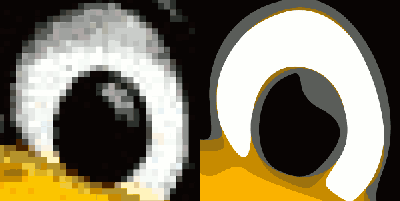
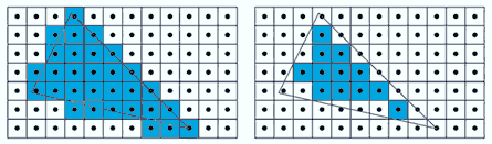
In fact, if we try to vectorize an image captured, for example, with a camera, the vectorization will have to perform color segmentation (“grouping” areas of similar colors) or we will end up with a vector image that is a rectangle for each pixel.
I think it illustrates quite well what was said above about continuous models, discrete models, sampling, and interpolation. So get ready because in 3D it’s the same (in fact, it’s even worse).
Conversion Processes Between 3D Representations
Let’s look at the different conversion processes, grouping by the model (discrete or continuous) of the origin and destination.
Discrete to Discrete
We start with the simplest and probably least interesting option. Converting from a mesh to a point object is easy. You simply have to create a point at each of the vertices of the mesh. And, except for very strange cases, it won’t be useful to us.
The opposite case is much more frequent and interesting. We have it every time we have to obtain a 3D model from a 3D scan (which, remember, always returns a point cloud).
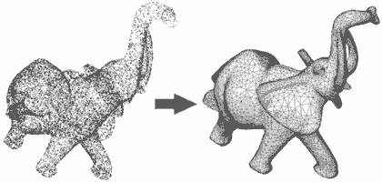
It is a process with high mathematical complexity and many studies done on it (it is still being studied today). There are several algorithms to perform this process, such as the well-known Delaunay, or the more commonly used Pivot-Ball along with variants.
But, in general, we can say that it is a process that is currently quite well solved and implemented in many 3D software.
Converting meshes to meshes is a much more common process than it might seem. Why would we want to convert one mesh into another? Well, to have a more convenient mesh, according to some criteria. This process is generally called retopology.
Examples are converting a mesh into one with a greater number of points, which includes subdivision or tessellation, at the cost of having a larger file size.
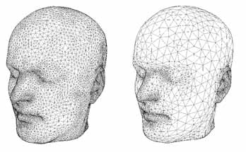
We also have the opposite process, mesh simplification, which reduces the number of points while trying to preserve detail. In general, algorithms are used that try to replace or eliminate polygons in areas of lower curvature.
But there are also other processes like smoothing, erosion, relaxation, “sharpening” (increasing details). Finally, in the field of video games, films, etc., retopology often seeks to obtain a mesh more suitable for animating or texturing.
Continuous to Continuous
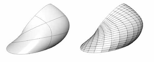
We already saw that, basically, a solid is made up of surfaces to which the concept of “inside and outside” has been added. Therefore, the conversion from solids to surfaces is practically immediate. This process can be called “decomposing” or “exploding”, depending on the 3D software.
The opposite case is not so simple, because not all surfaces generate a solid. In general, if we have a closed surface without singular points (closed loops on themselves, and other anomalies) the process is possible.
If instead of a single surface we have several, we must join them and treat them with the available surface tools until we have a valid model to convert into a solid.
There is no standard name for this conversion, but sometimes we will see the operation referred to as “solidify” or simply “convert to solid” in 3D software.
Continuous to Discrete
We enter the most interesting processes. The conversion of surfaces/solids is a very frequent and normal process, more than it might seem. Your computer does it every time it displays a CAD model on your screen, since the GPU is designed to work with meshes.
In our case, our 3D printer is not capable of working with solids or surfaces (it might surprise you, but most industrial manufacturing processes aren’t either). So to print our CAD files we have to convert them into triangulated files (usually to STL).
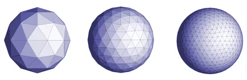
Fortunately, as we anticipated, in general this triangulation process is relatively straightforward. There are different algorithms (uniform, spatial, curvature-based) to obtain a mesh from a solid or surface.
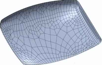
Like any sampling process, triangulation is a lossy process. We are representing objects, with curves with (theoretically) infinite detail, by a series of triangles with straight sides. If the triangles are small enough, we won’t notice the difference, at a certain distance.
If we want to increase the quality, we have to reduce the size of the triangles. Most CAD software allows configuring the level of detail when exporting to meshes. But, as we have advanced, this implies a larger file size and processing time. As usual, the important thing is to reach a compromise in precision and quality.
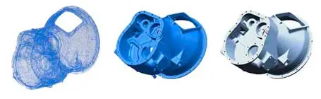
Discrete to Continuous
We arrive at the most difficult case: converting a meshed surface into a surface/solid. This process is called reverse engineering and, in general, it is not a simple process and requires human intervention to obtain good results.
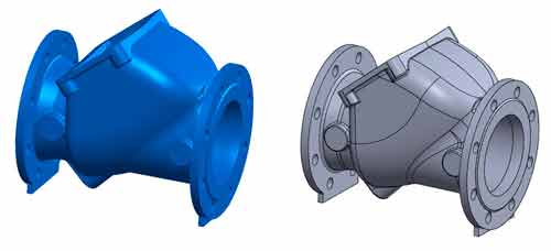
It must be taken into account that in a triangulated mesh, and especially in those that come from real-world capture/scanning, the curves are polygonal approximations. But it’s even worse, the planes are not planes either. We need to interpolate and fit surfaces to the points.
There are dedicated programs that provide assistance in the process, and most CAD software are beginning to incorporate functions to work with meshed models, providing tools that help perform this process.
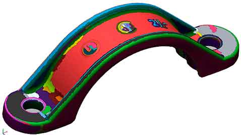
There are also “automatic” processes that convert the mesh into a series of surfaces that approximate the original object. It may be enough to work with them in CAD software, but it is not (by any means) a perfect solid like the one we would have if we had drawn it.
On the other hand, even if we use the tools to fit surfaces (planes, cylindrical, conical) from the reverse engineering tools, in most cases the result is still not perfect. The radius that (by logic) in the original design was 50mm, after fitting and measuring is 50.13mm. Two cylinders that were concentric are no longer so. The same with parallelisms, perpendicularities, symmetries, patterns, etc.
In principle, the complete reverse engineering process requires “almost” completely redrawing the part using the model as a base. Sometimes it takes even longer than drawing it from scratch, because when you draw it from scratch you do it “as you want” and in reverse engineering you have to adjust to a model.
That’s it for this pair of posts aimed at introducing the basis of 3D object representation and their conversion processes, as a preliminary to diving fully into the world of 3D design and printing.
In the next posts in the section, we will delve into 3D design by presenting the different types of 3D design software and the main CAD design software. See you soon!