In the previous post we saw what interrupts are and how to use them to respond to hardware events on pins.
We also made it clear that physical devices, such as pushbuttons, optical sensors, etc., exhibit a bounce effect that interferes with the use of interrupts, and that we need to eliminate it or we won’t be able to use interrupts with these devices.
The process of eliminating this bounce is called “debounce”. In this post, we will learn what bounce is and how to eliminate it using hardware and software debounce.
What is Debounce?
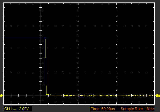
Electronic devices when changing state generate a signal that, while not perfectly square, is generally more or less “clean”. Let’s see, for example, the signal generated by Arduino when changing the state of a digital output from HIGH to LOW.
However, the real world is not so nice. Many physical devices often generate noise on the signal edges. As an example, let’s look at the voltage variation that occurs when the state change is generated by a pushbutton.
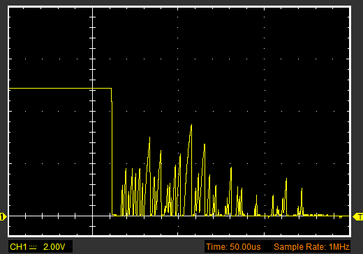
Notice the amount of noise after the edge. Essentially, in the range of a few microseconds, the signal is pure noise. All those spikes can cause multiple interrupt triggers.
Testing Bounce
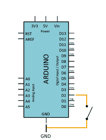
To test bounce, we will simply use a wire to connect Pin 2 and Ground (you can also use a pushbutton or a switch).
We enable the internal Pull UP resistor on Pin 2 and define an interrupt for the FALLING event on the PIN, and in the associated ISR function we simply increment a counter.
In the main loop, we check the counter, and if it has been modified, we display its value via the serial port.
const int intPin = 2;
volatile int ISRCounter = 0;
int counter = 0;

void setup()
{
  pinMode(intPin, INPUT_PULLUP);
  Serial.begin(9600);
  attachInterrupt(digitalPinToInterrupt(intPin), debounceCount, FALLING);
}

void loop()
{
  if (counter != ISRCounter)
  {
    counter = ISRCounter;
    Serial.println(counter);
  }
}

void debounceCount()
{
  ISRCounter++;
}
When testing our setup and connecting PIN 2 to GROUND, we would expect the variable to increment one by one. But we will see that it actually jumps several numbers each time (even several tens).
This is the bounce effect. The signal noise is generating multiple interrupts each time we connect the wire.
Eliminating Bounce
We have two ways to apply debounce. By adding electronic devices that filter the signal (hardware debounce) or by modifying our code to eliminate the bounce (software debounce).
Hardware Debounce
Applying hardware debounce has the advantage of not increasing the execution time of our code. Furthermore, it is generally a more robust solution. On the downside, it increases the complexity of our setup.
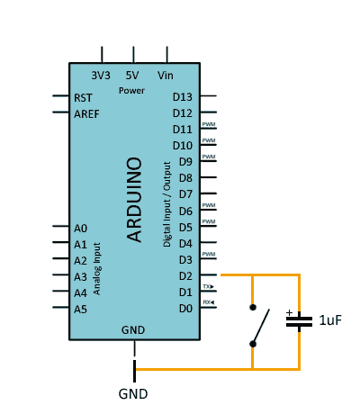
The simplest way to apply hardware debounce is to place a capacitor in parallel with the device (pushbutton, switch, sensor…). A capacitor on the order of 1uF should be sufficient to filter most of the noise.
The connection diagram is as follows.
In general, it is always advisable to add a hardware filter when using physical inputs with interrupts.
Software Debounce
Software debounce has the advantage of not requiring additional components. We solve the bounce solely by modifying our program’s code.
As a disadvantage, it slightly increases execution time and code complexity. Also, if we don’t apply the code correctly, we can ignore “true” interrupts.
The simplest way to apply software debounce is to check the time between interrupt triggers. If the time is less than a certain time threshold, we simply ignore the interrupt. In short, we have defined a “dead zone” where we ignore generated interrupts.
To apply software debounce, we modify the ISR function as follows.
const int timeThreshold = 150;
const int intPin = 2;
volatile int ISRCounter = 0;
int counter = 0;
long startTime = 0;

void setup()
{
  pinMode(intPin, INPUT_PULLUP);
  Serial.begin(9600);
  attachInterrupt(digitalPinToInterrupt(intPin), debounceCount, FALLING);
}

void loop()
{
  if (counter != ISRCounter)
  {
    counter = ISRCounter;
    Serial.println(counter);
  }
}

void debounceCount()
{
  if (millis() - startTime > timeThreshold)
  {
    ISRCounter++;
    startTime = millis();
  }
}
A time of 100-200ms is correct for a pushbutton, but in other cases we will need to adjust the time so that we eliminate the bounce, but do not ignore two possible close “true” events.
In a real setup, the best is to use a combination of both systems, while correctly adjusting the capacitor value and the software filter times to adapt them to our system.
Download the Code
All the code from this post is available for download on Github. 
