What is a Hall sensor?
A Hall sensor is a device that allows us to measure magnetic field.
Hall sensors are widely used. For example, in the automotive industry, they are used for functions as diverse as the operation of seat belts or the measurement of the camshaft position. They are also used to measure fluid speeds, detect metals, induction factors, among many other applications.
An important advantage of Hall sensors is that they measure from a distance, without the need for physical contact. Although their range is limited (typically a few centimeters), this means that they present almost no mechanical wear. They are also immune to noise and dust. This makes them reliable and durable sensors.
In general, we find two types of Hall sensors:
- Analog: They generate an output proportional to the intensity of the magnetic field. Used to measure the intensity of a magnetic field
- Digital: They provide a high value in the presence of a magnetic field, and a low value in the absence of it. Therefore, they are used to detect the existence of magnetic fields. They are further divided into,
- Switch, they are activated when the pole is brought close, and deactivated when the pole is removed
- Latch, they are activated when a pole is brought close, and maintain their value until an opposite pole is brought close
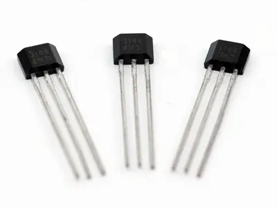
In this post, we will use a Hall A3144 sensor, of the digital Switch type. We can use this sensor to detect the presence of an object, to which we will have previously placed a small magnet, or to make tachometers (revolution counters) simply by attaching a small neodymium magnet to the shaft.
Price
Hall A3144 sensors are really cheap. We can find 10 A3144 devices for €0.6 on international sellers on eBay or AliExpress.
How does a Hall sensor work?
Its principle of operation is the Hall effect, named after its discoverer Edwin Herbery Hall, in 1849.
By passing an electric current through a semiconductor in the presence of a magnetic field, the electrons are deflected by the magnetic field, resulting in a voltage perpendicular to the current and the magnetic field.
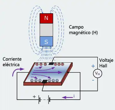
By measuring this voltage generated by the Hall effect, we can build sensors and magnetic field meters.
Electrical schematic
The electrical schematic we need is as follows.
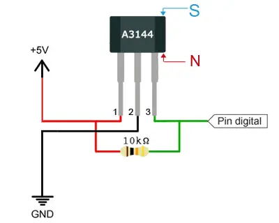
So, the connection scheme with Arduino would be like this.
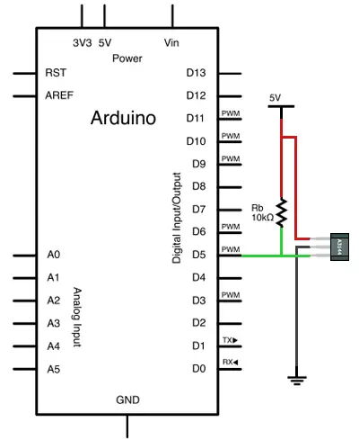
The schema and resistor values shown correspond to the A3144 sensor. Other Hall sensors require different assembly schemes. Check their corresponding datasheet if your component is different.
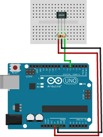
Assembly
While the assembly on a breadboard would be as follows.
Code example
The code needed to perform the reading is simple. We simply read the state of the Hall sensor Pin, as we saw in the entry digital inputs on Arduino.
const int HALLPin = 5;
const int LEDPin = 13;

void setup() {
  pinMode(LEDPin, OUTPUT);
  pinMode(HALLPin, INPUT);
}

void loop() {
  if(digitalRead(HALLPin)==HIGH)
  {
    digitalWrite(LEDPin, HIGH);
  }
  else
  {
    digitalWrite(LEDPin, LOW);
  }
}
Download the code
All the code from this post is available for download on Github. 
