What is an IR obstacle detector?
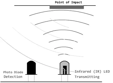
An infrared obstacle detector is a device that detects the presence of an object by the reflection it produces in the light. The use of infrared light (IR) is simply so that it is not visible to humans.
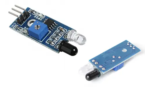
Constitutively, they are simple sensors. They have an infrared LED emitter and a photodiode (type BPV10NF or similar) that receives the light reflected by a potential obstacle.
 Obstacle detectors are usually provided with a standard measurement board with the LM393 comparator, which allows obtaining the reading as a digital value when a certain threshold is exceeded, which is regulated through a potentiometer located on the board.
These types of sensors operate at short distances, typically 5 to 20mm. In addition, the amount of infrared light received depends on the color, material, shape, and position of the obstacle, so they do not have sufficient accuracy to provide an estimate of the distance to the obstacle.
Despite this limitation, they are widely used for obstacle detection in small vehicles or robots. Their low cost makes it common to place them around the perimeter, so that we can detect obstacles in several directions.
They are also useful in other types of applications such as, for example, detecting the presence of an object in a certain area, determining whether a door is open or closed, or if a machine has reached a certain point in its movement.
Price
Infrared obstacle sensors are really cheap. We can find infrared detectors, including the measuring board, for €0.30 from international sellers on eBay and AliExpress.
Being a simple sensor, we can also assemble it ourselves. In general, it is not worth it since only the components would cost us more, not counting the time and the quality we could obtain, so it is normal for us to use a commercial model.
Electrical schematic
The assembly is simple. We power the module through Vcc and GND by connecting them, respectively, to the 5V and GND output on Arduino.
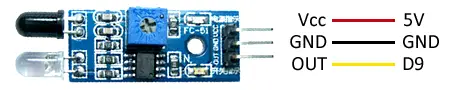
Finally, we connect the digital output of the sensor to a digital input to read the state of the sensor.
Optionally, we calibrate the trigger threshold by bringing an object closer to the obstacle detector and adjusting the digital output with the potentiometer. If you want to skip this step, leave the potentiometer at a medium value.
Code examples
The code is equally simple. We simply read the state of the digital input, just as we saw in the entry Digital inputs in Arduino.
If the sensor is triggered, we execute the necessary actions.
const int sensorPin = 9;

void setup() {
  Serial.begin(9600);   //initiate serial port
  pinMode(sensorPin , INPUT);  //define pin as input
}

void loop(){
  int value = 0;
  value = digitalRead(sensorPin );  //digital reading of pin

  if (value == HIGH) {
      Serial.println("Obstacle detected");
  }
  delay(1000);
}We can also read the state of the sensor using interrupts. For more information, consult the entry What are and how to use interrupts in Arduino and Reading a button with interrupts in Arduino
Download the code
All the code in this post is available for download on Github.

