One of the most interesting functions (if not the most) of Arduino and generally of all programmable logic controllers is their ability to interact with the physical world.
We can, for example, take voltage measurements, obtain readings from a wide variety of sensors, turn devices on or off, or control motors and actuators.
This interaction is largely carried out through the use of both digital and analog inputs and outputs. In the following posts we will learn how to use these functions.
Let’s start with digital inputs, because they are the simplest (although we will see later that the other functions are not much more complicated).
Although we are using Arduino as a platform, it is important to note that most of the concepts are applicable to any general programmable logic controller. At the end we will see the code and setup for Arduino, but first we will briefly look at some general theory.
What is a digital input?
A digital signal is a voltage variation between -Vcc and +Vcc without passing through intermediate values (for example, 0V and 5V).
Therefore, a digital signal has only two states:
- We associate the lower value -Vcc with a logical value
LOWor logical0. - We associate the higher value +Vcc with
HIGHor logical1.
Of course, in the physical world, voltage signals are actually continuous. There is no signal that “magically jumps from one voltage to another.”
The digital reading process is a discretization process. We convert an analog measurement (the value of the voltage we measure) into a digital (“fictitious”) signal.
Making this conversion is not very difficult. A digital input compares the actual measurement with a threshold voltage value.
- If the measured value is higher than the threshold voltage, it returns
HIGH. - If the measured value is lower, it returns
LOW.
The threshold voltage value varies from one controller to another, and it doesn’t even have to remain constant over time. But, in general, it is normal for the threshold voltage to be close to the midpoint between -Vcc and +Vcc.
However, we should avoid measuring voltages near the threshold voltage because they can cause incorrect readings.
Digital Inputs in Arduino
In Arduino, digital inputs and outputs share the same PIN. For this reason, they are called digital I/Os (input / output).
This means that the same pin can perform both input and output functions, although, logically, not simultaneously. It is necessary to configure an I/O pin as an input or output (in our program).
Arduino has a different number of digital I/Os depending on the model, as we saw in the post What is Arduino? Which model to buy?. For example, Arduino UNO has 16 digital I/Os and Arduino MEGA has 54.
In Arduino, the usual supply values are 0V and 5V. In this case, the threshold voltage will be very close to 2.5V. Therefore:
- If we measure a voltage with a value between 0V and 2.5V, Arduino will return a
LOWreading. - If we measure a value between 2.5V and 5V, it will return
HIGH.
Never apply a voltage outside the range of 0V to 5V to a digital or analog input or we may damage the corresponding pin and permanently render it unusable.
Connecting Digital Inputs
Suppose we want to use Arduino to connect it to a sensor, or any other device, that has a continuous voltage output between 0V and 5V.
For now, we are not considering the possibility of the digital input being completely disconnected, something we will cover in the next post “Reading a Button with Arduino”.
We can read the voltage value from the sensor with a schematic like the following.
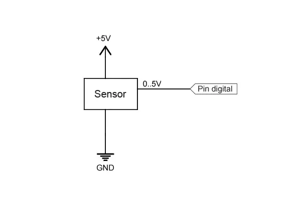
The reading will give a value:
HIGHif the voltage value is above the threshold voltage (2.5V).LOWif the voltage value is below it.
Code in Arduino
The code to perform the reading is really simple. We simply have to configure a digital I/O as an input with pinMode() and perform the reading with digitalRead().
int pin = 2;
int value = 0;

void setup() {
  Serial.begin(9600);   //start serial port
  pinMode(pin, INPUT);  //define pin as input
}

void loop(){
  value = digitalRead(pin);  //digital reading of pin

  //send message to serial port based on the read value
  if (value == `HIGH`) {
      Serial.println("On");
  }
  else {
      Serial.println("Off");
  }
  delay(1000);
}Pins configured as inputs are in a high-impedance state, meaning they behave like very high-value resistors (on the order of 100 megaohms). Therefore, a negligible current flows through them.
Actually, Arduino (Atmega) pins are initialized as inputs by default, so it is not strictly necessary to configure them as inputs, although it is a convenient practice.
Reading Values Greater Than 5V
We have mentioned that under no circumstances should we apply a voltage outside the 0 to 5V range to an Arduino pin or we risk permanently damaging it.
If we want to measure a voltage level higher than the supply limits, the most convenient way is to use a simple voltage divider.
For example, to read a digital signal between 0 to 12V we can use a schematic like the following.
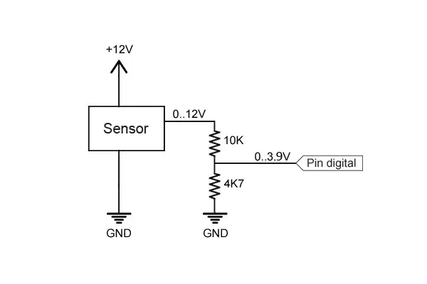
With this configuration, the Arduino digital pin will receive a voltage varying between 0 to 3.84V, enough to trigger the threshold voltage, and below the supply limit.
The resistor values to use depend on the voltage we want to read, and on the sensor’s impedance.
In general, they must meet the following conditions:
- Provide a voltage higher than the threshold voltage.
- Be much higher than the equivalent impedance of the device being measured.
- Be negligible compared to the impedance of the Arduino input.
- Limit the current flowing through them to minimize losses.
- Be capable of dissipating the power they will handle.
You can use the voltage divider calculator to calculate resistor values that meet these requirements.
In the next post, we will see how to use the digital input to read the state of a button.
Do not use this system to read voltages above 35V, or for alternating current devices without being very sure of what you are doing. It is very likely that the resistors will not withstand it.
Download the Code
All the code from this post is available for download on Github.

